Solar cell evaluation method, evaluation device, maintenance method, maintenance system, and method of manufacturing solar cell module

a solar cell and defect technology, applied in the direction of optical radiation measurement, image enhancement, instruments, etc., can solve the problems of preventing efficient production of solar cells with high performance and high reliability, affecting the performance and reliability of solar cells, and affecting the quality of solar cells, etc., to achieve easy evaluation of solar cell quality, easy to distinguish among defects of solar cells, and large facilities

Inactive Publication Date: 2014-04-15
NARA INSTITUTE OF SCIENCE AND TECHNOLOGY
View PDF8 Cites 3 Cited by
  • Summary
  • Abstract
  • Description
  • Claims
  • Application Information

AI Technical Summary

Benefits of technology

[0025]The method and device of the present invention for evaluating a solar cell produces an effect that it is possible to easily distinguish among defects of the solar cell, especially between an internal cause defect caused due to physical properties of the solar cell and an external cause defect which is a mechanical defect. This makes it possible to evaluate type and / or quantity of defects of the solar cell. Further, since the present invention utilizes electroluminescence, a large facility is not necessary. It is therefore possible to evaluate the solar cell as a product (as a product completed in the manufacturing factory or as a product implemented on a construction).
[0026]Further, the solar cell maintenance method and maintenance system of present invention do not require a large-sized device, and make it possible to evaluate quality of a solar cell easily. It is therefore possible to regularly perform maintenance of even a solar cell implemented on a construction. Consequently, quality of a solar cell module can be kept at a certain level.
[0027]Further, according to the method of the present invention for producing a solar cell module, it is possible to detect defects while distinguishing between an internal cause defect and an external cause defect. Accordingly, it is possible to repair or replace only a serious defective part. This produces an effect that a solar cell module can be produced efficiently.

Problems solved by technology

However, in production process of a solar cell, it is difficult to avoid occurrence of defects in the solar cell.
This prevents efficient production of solar cells having high performance and high reliability.
Further, if defects occur in a solar cell that has been installed during use of the solar cell, performance and reliability of the solar cell decline.
The internal cause defects are defects such as crystal defect, dislocation, grain boundaries and the like that are caused by physical properties of a solar cell.
The internal cause defects affect functions of a solar cell, but do not affect reliability of materials constituting the solar cell very much.
Meanwhile, the external cause defects are mechanical defects of solar cells such as a substrate crack (e.g., microcrack), electrode rupture, loose connection and the like.
The external cause defects cause adverse effect on reliability of solar cells and production yield of solar cells, and therefore become deciding factors in efficient mass production of highly reliable solar cells.
As described above, internal cause defects cause a decline in performance of a solar cell, and causes a deterioration in power generation efficiency of the solar cell if left untreated, but an influence of the internal cause defects is small in terms of long-term reliability.
Meanwhile, if external cause defects are left untreated, reliability gradually declines, and in the worst case, a solar cell is broken.
Accordingly, external cause defects cause a greater adverse effect than internal cause defects.
However, in the conventional arts, it is impossible to distinguish between an internal cause defect and an external cause defect.

Method used


Image

  • Solar cell evaluation method, evaluation device, maintenance method, maintenance system, and method of manufacturing solar cell module
  • Solar cell evaluation method, evaluation device, maintenance method, maintenance system, and method of manufacturing solar cell module
  • Solar cell evaluation method, evaluation device, maintenance method, maintenance system, and method of manufacturing solar cell module

Examples


example

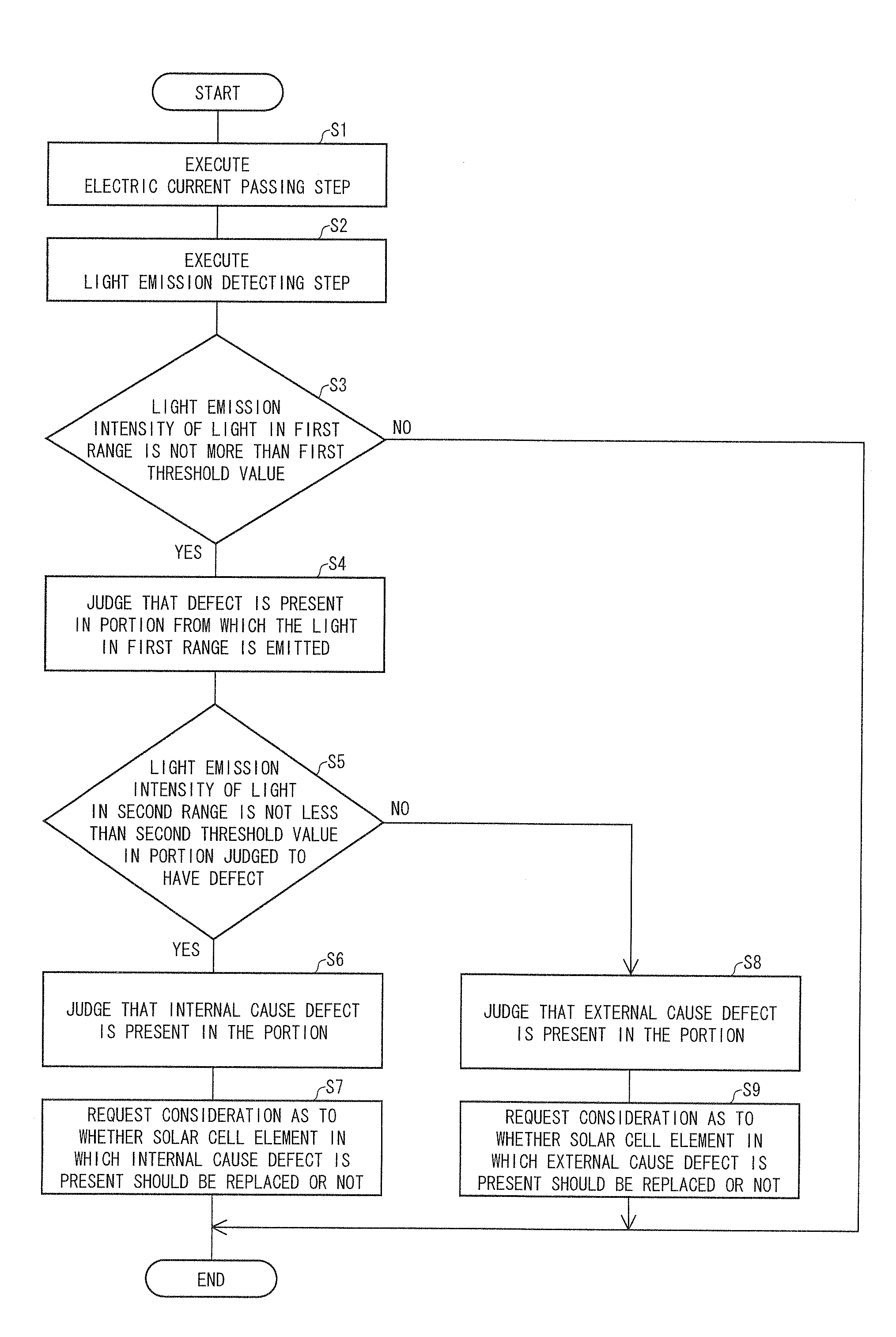
[0244]An electric current was passed, in a forward direction, through a solar cell module including a plurality of solar cell elements made from a polycrystalline silicon semiconductor, and light generated due to the passage of the electric current was analyzed. In the present Example, an InGaAs CCD camera (Xenics, XEVA-1.7 series) was used to picture this light.

[0245]First, light emission intensity (luminescence intensity) and spectral characteristics of light generated by passing an electric current of 40 mA / cm2 through the solar cell module was analyzed. The result is shown in (a) of FIG. 11. Note that the spectral characteristics were measured with the use of a spectrometer (JASCO Corp. M50) according to its operation manual. The broken line in (a) of FIG. 11 indicates a wavelength range (wavelengths in a range from 200 nm to 1200 nm) of light detected with the use of a Si CCD camera, and the dashed-dotted line in (a) of FIG. 11 indicates a wavelength range (wavelengths in a ran...


PUM

PropertyMeasurementUnit
wavelengthsaaaaaaaaaa
wavelengthaaaaaaaaaa

Abstract

A method and device for evaluating a solar cell each of which makes it possible to easily evaluate a defect of a solar cell especially in such a manner that an internal cause defect and an external cause defect are distinguished from each other. The device includes: electric current passing means for passing, in a forward direction, an electric current through a solar cell element constituting the solar cell; light emission detecting means for detecting, out of light emitted from the solar cell element due to the electric current passed by the electric current passing means, light in a first range of wavelengths from 800 nm to 1300 nm and light in a second range of wavelengths from 1400 nm to 1800 nm; and judging means for distinguishing between an internal cause defect and an external cause defect.

Description

[0001]This application is the U.S. national phase of International Application No. PCT / JP2010 / 063073 filed 3 Aug. 2010 which designated the U.S. and claims priority to JP 2009-181850 filed 4 Aug. 2009, the entire contents of each of which are hereby incorporated by reference.TECHNICAL FIELD[0002]The present invention relates to method and device for evaluating a defect of a solar cell easily, and use thereof. Especially, the present invention relates to method and device for evaluating a defect of a solar cell easily by passing an electric current through solar cell elements constituting the solar cell, and analyzing characteristics of light emitted due to the electric current passage, and use thereof.BACKGROUND ART[0003]For keeping the environment of the earth, use of solar energy is getting popular. Solar cells are implemented on more and more roofs or walls of ordinary buildings and houses. Among the solar cells, development and production of solar cells which incorporate semicon...

Claims


Application Information

Patent Timeline
Patent Type & Authority Patents(United States)
IPC IPC(8): G01N21/66G01N21/95G01J5/00G01R31/26G01N21/00
CPCY02E10/50G01N21/9505G01N21/88H01L31/186G01R31/2605G01N21/66G06T2207/10048G01R31/308H02S50/10Y02P70/50
Inventor FUYUKI, TAKASHITANI, AYUMI
Owner NARA INSTITUTE OF SCIENCE AND TECHNOLOGY
Why Eureka
Try Eureka