Estimation of panoramic camera orientation relative to a vehicle coordinate frame

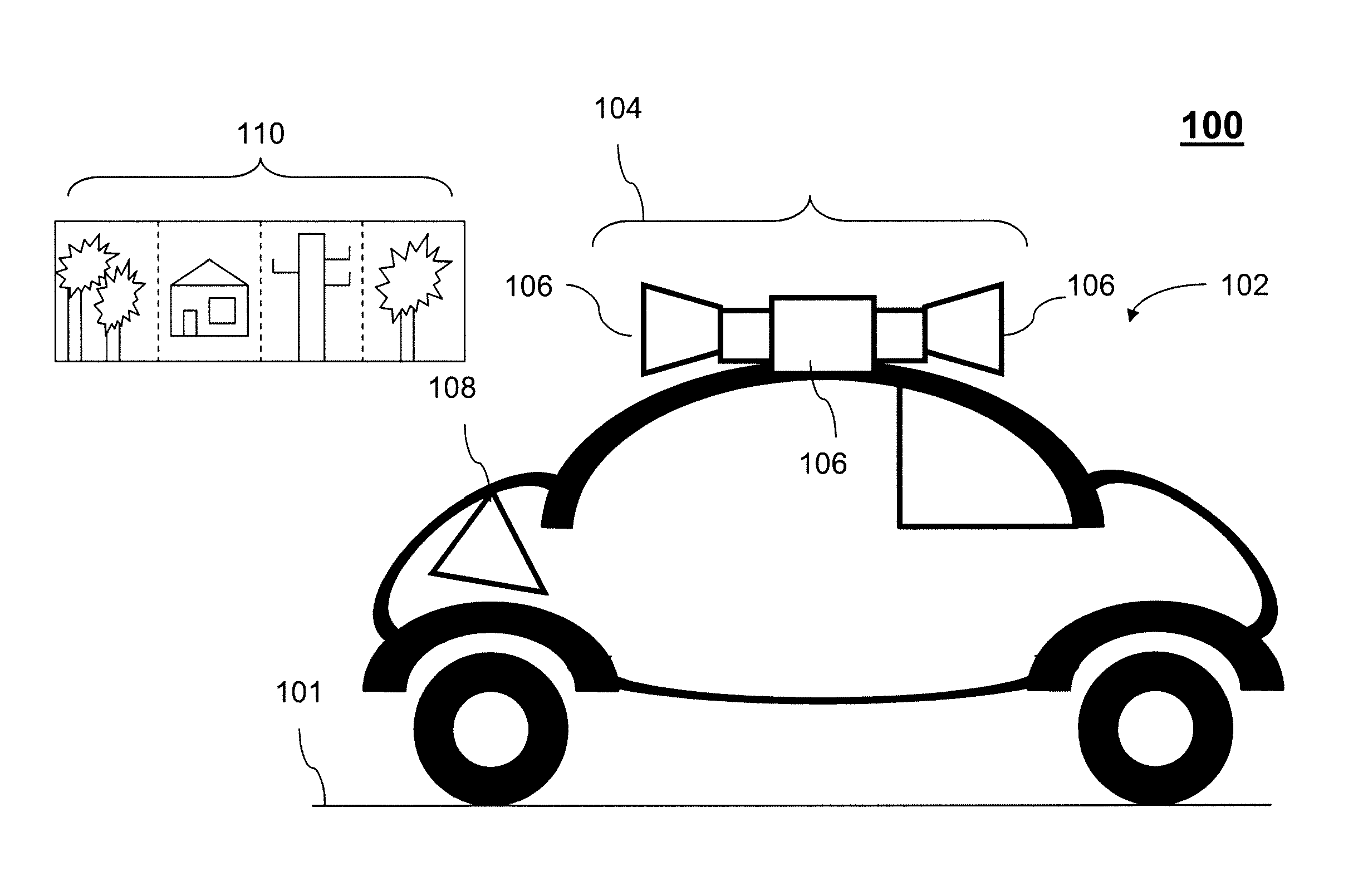
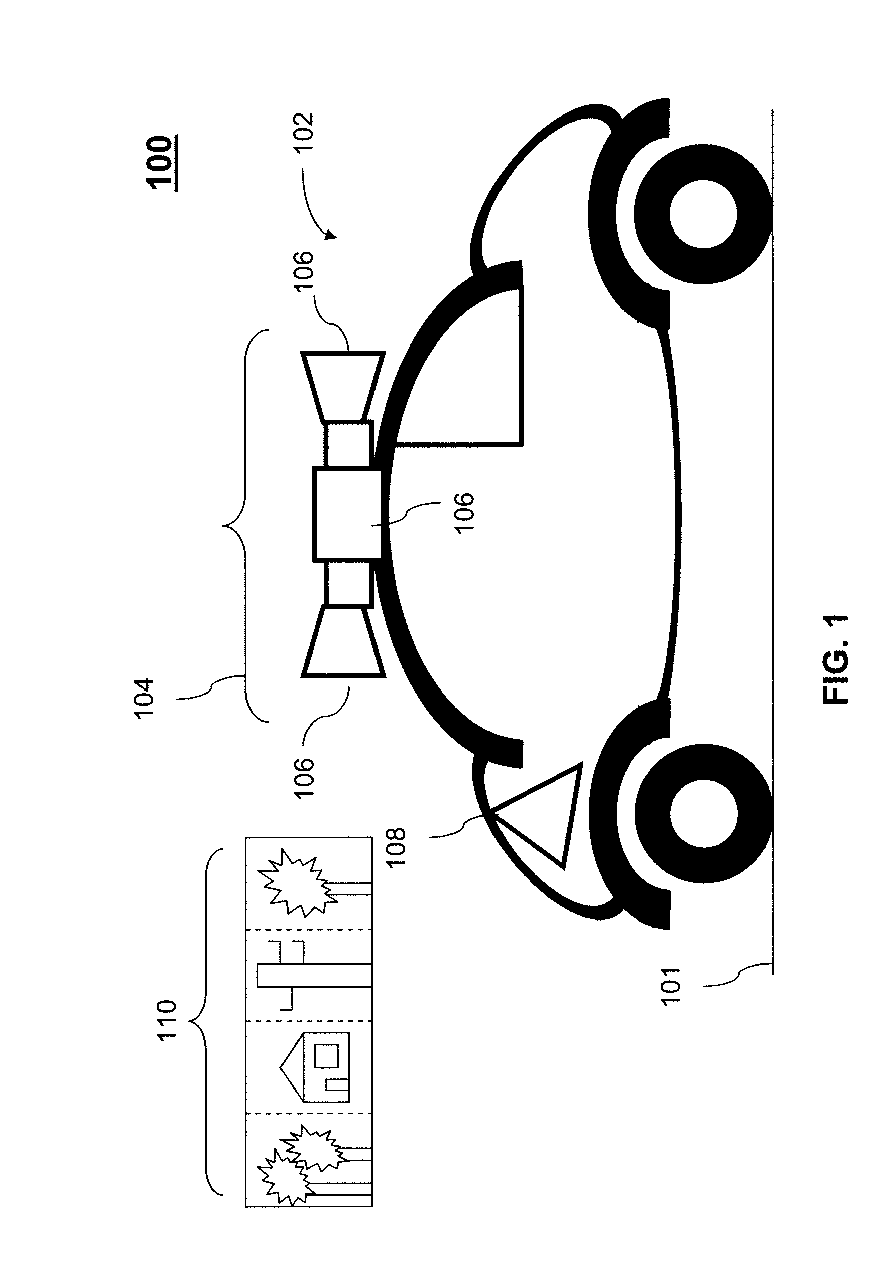
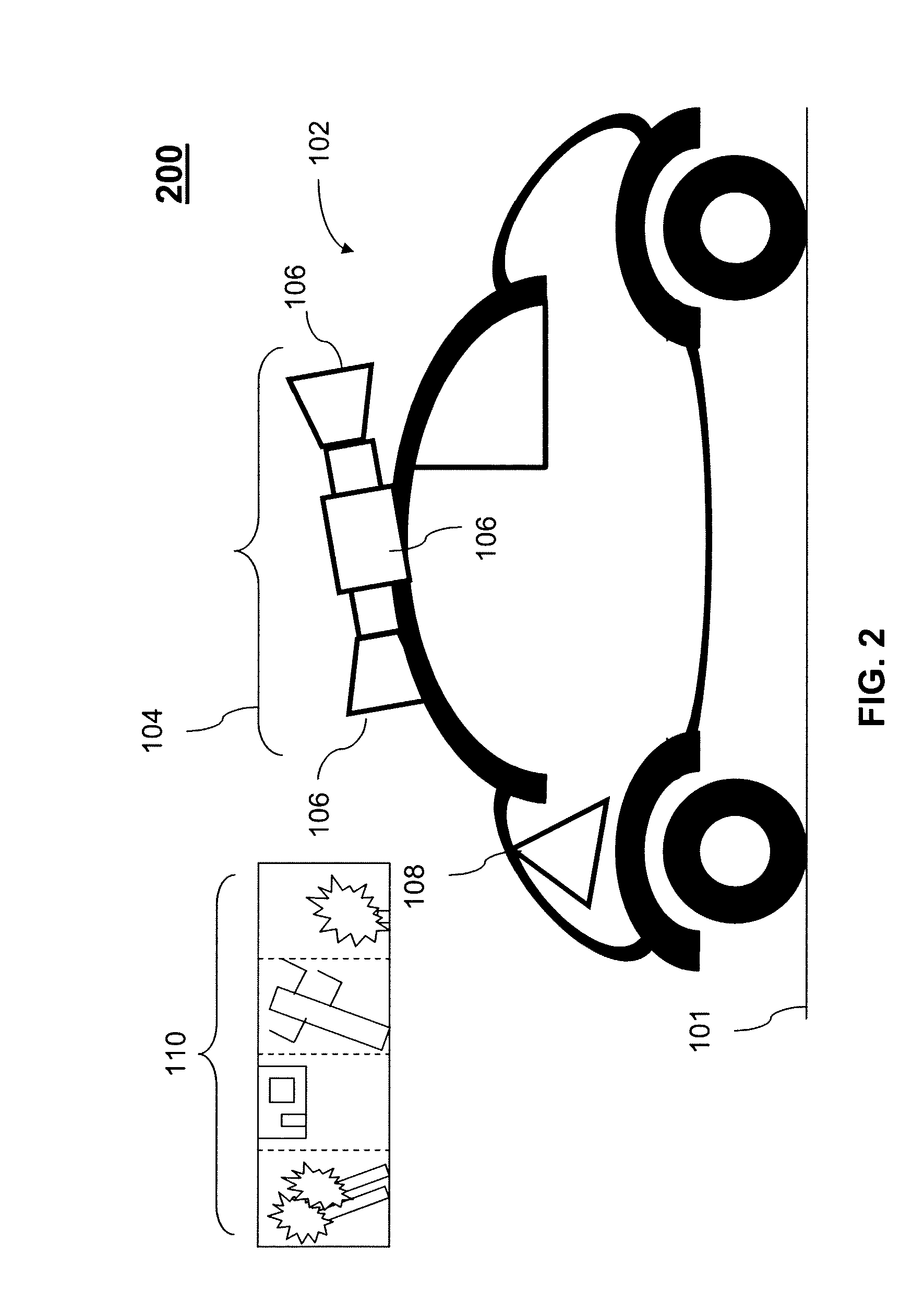
a panoramic camera and coordinate frame technology, applied in the field of cameraobtained imagery, can solve the problems of little consistency in the placement of the camera rack on the top of the vehicle roof, objects (e.g., buildings) and their surroundings may appear incorrectly, and the directional arrows that may be used in the viewing tool may point in the wrong direction

Inactive Publication Date: 2014-04-15
GOOGLE LLC
View PDF14 Cites 18 Cited by
  • Summary
  • Abstract
  • Description
  • Claims
  • Application Information

AI Technical Summary

Problems solved by technology

For example, there is little consistency in the placement of a camera rack on top of the vehicle roof.
If this information is not known or inaccurate, objects (e.g., buildings) and their surroundings may appear incorrectly, e.g., tilted to one side.
Furthermore, directional arrows that may be used in a viewing tool may point in a wrong direction.

Method used


Image

  • Estimation of panoramic camera orientation relative to a vehicle coordinate frame
  • Estimation of panoramic camera orientation relative to a vehicle coordinate frame
  • Estimation of panoramic camera orientation relative to a vehicle coordinate frame

Examples


Embodiment Construction

[0028]While the present invention is described herein with reference to illustrative embodiments for particular applications, it should be understood that the invention is not limited thereto. Those skilled in the art with access to the teachings provided herein will recognize additional modifications, applications, and embodiments within the scope thereof and additional fields in which the invention would be of significant utility.

[0029]It is noted that references in the specification to “one embodiment,”“an embodiment,”“an example embodiment,” etc., indicate that the embodiment described may include a particular feature, structure, or characteristic, but every embodiment may not necessarily include the particular feature, structure, or characteristic. Moreover, such phrases are not necessarily referring to the same embodiment. Further, when a particular feature, structure, or characteristic is described in connection with an embodiment, it would be within the knowledge of one skil...


PUM


Abstract

A system and method are presented for estimating the orientation of a panoramic camera mounted on a vehicle relative to the vehicle coordinate frame. An initial pose estimate of the vehicle is determined based on global positioning system data, inertial measurement unit data, and wheel odometry data of the vehicle. Image data from images captured by the camera is processed to obtain one or more tracks, each track including a sequence of matched feature points stemming from a same three-dimensional location. A correction parameter determined from the initial pose estimate and tracks can then be used to correct the orientations of the images captured by the camera. The correction parameter can be optimized by deriving a correction parameter for each of a multitude of distinct subsequences of one or more runs. Statistical analysis can be performed on the determined correction parameters to produce robust estimates.

Description

CROSS-REFERENCE TO RELATED APPLICATIONS[0001]This application claims the benefit of priority to U.S. Provisional Patent Application No. 61 / 177,614, filed May 12, 2009, and to U.S. Provisional Patent Application No. 61 / 154,217, filed Feb. 20, 2009, both entitled “Estimation of Panoramic Camera Orientation Relative to a Vehicle Coordinate Frame,” and both incorporated herein by reference in their entireties.BACKGROUND[0002]1. Field of the Invention[0003]The present invention relates to camera-obtained imagery captured from a moving vehicle.[0004]2. Related Art[0005]A camera, such as a panoramic camera, can be mounted on a vehicle, such as a car, truck, van, or any kind of vehicle, and used to capture images as the vehicle moves. A panoramic camera is a camera, typically a system of one or multiple cameras, that is configured or arranged to capture a panoramic image (i.e., an image or view of an area in many directions, possibly every direction). Examples of a panoramic camera can incl...

Claims


Application Information

Patent Timeline
Patent Type & Authority Patents(United States)
IPC IPC(8): H04N7/18H04N7/00
CPCH04N5/23296G06T2207/30252G06T7/004H04N5/23238H04N5/2628G06T7/70H04N23/69H04N23/698
Inventor ANGUELOV, DRAGOMIR D.FILIP, DANIEL
Owner GOOGLE LLC
Why Eureka
Try Eureka