Occupant detection sensor including a bent portion and a stress absorbing portion and method of manufacturing the same

a technology of occupant detection and bending, which is applied in the direction of tractors, instruments, chairs, etc., can solve the problems of sensor damage, film sensor may be subjected to a load, and cannot detect sitting at the thigh, so as to maintain the accuracy of the sensor and restrict the damage of the sensor

Active Publication Date: 2014-04-22
DENSO CORP
View PDF21 Cites 5 Cited by
  • Summary
  • Abstract
  • Description
  • Claims
  • Application Information

AI Technical Summary

Benefits of technology

[0009]In view of the foregoing problems, it is an object of the present invention to provide an occupant detection sensor that can maintain an accuracy of a sensor member and can restrict damage of the senor member. Another object of the present invention is to provide a method of manufacturing an occupant detection sensor that can absorb stress generated by bending of a portion of a coupling section.
[0011]In the occupant detection sensor, even when stress is generated at the bent portion, the stress absorbing portion absorbs the stress. Thus, the occupant detection sensor can maintain an accuracy of the sensor member and can restrict damage of the sensor member.

Problems solved by technology

Thus, the film sensor can detect sitting at a buttock but cannot detect sitting at a thigh.
For example, even when a child stands in the vicinity of a backrest of a vehicle seat, the film sensor may be subjected to a load and may detect sitting of an occupant by error.
Furthermore, because the sensor is continuously pressed down by the seat cover, the sensor may be damaged (for example, peeling off of the film or a silver layer) when a stress generated by bending exceeds a tolerance.

Method used


Image

  • Occupant detection sensor including a bent portion and a stress absorbing portion and method of manufacturing the same
  • Occupant detection sensor including a bent portion and a stress absorbing portion and method of manufacturing the same
  • Occupant detection sensor including a bent portion and a stress absorbing portion and method of manufacturing the same

Examples


first embodiment

[0063](First Embodiment)

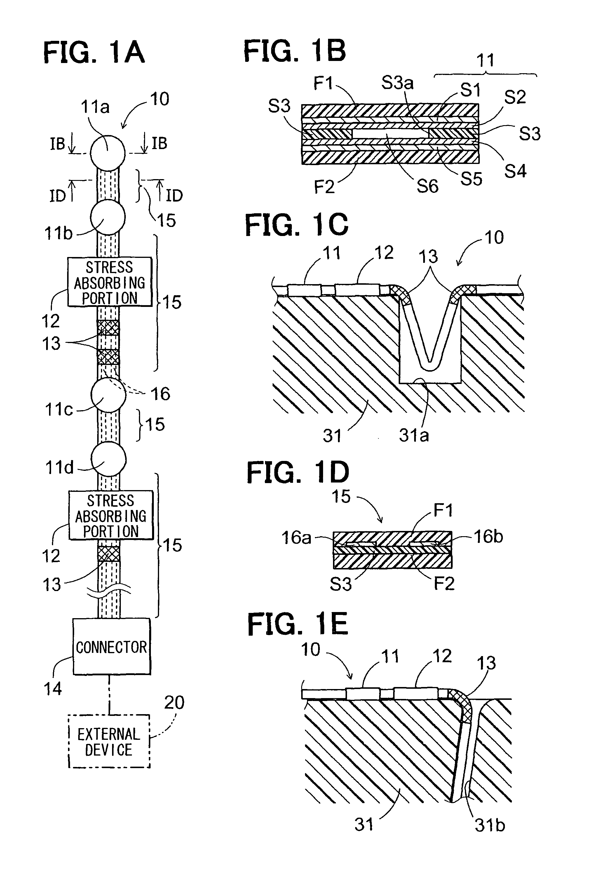
[0064]An occupant detection sensor 10 according to a first embodiment will be described with reference to FIG. 1A to FIG. 4D. The occupant detection sensor 10 includes a stress absorbing portion formed into a wavy shape.

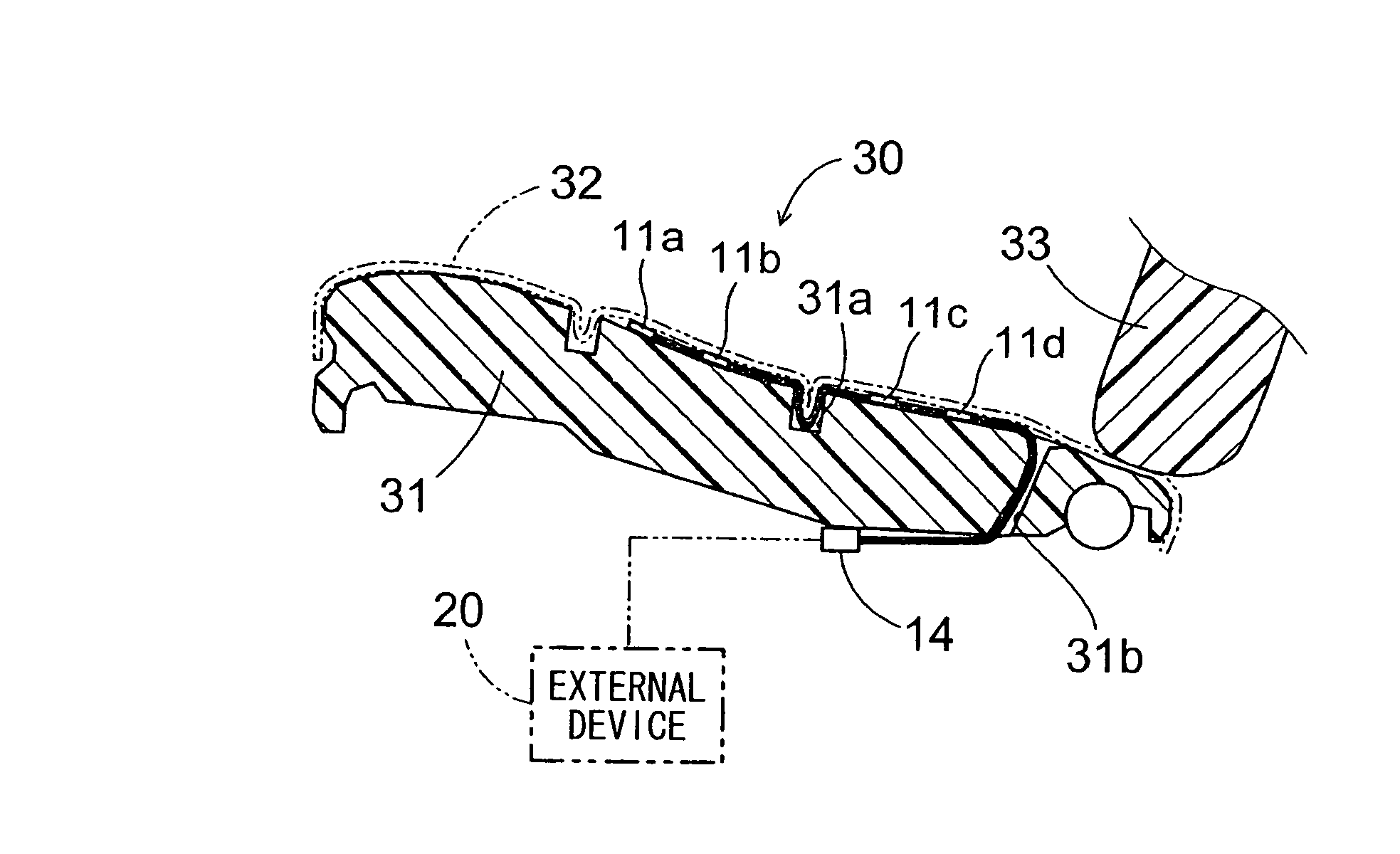
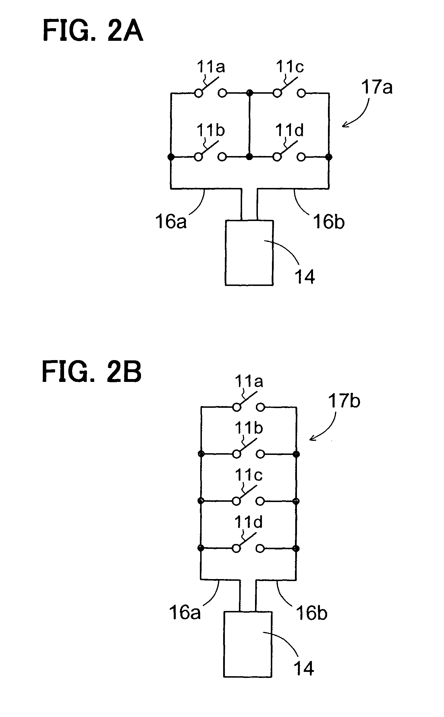
[0065]The occupant detection sensor 10 includes one or more sensor members 11, one or more stress absorbing portions 12, one or more bent portions 13, a connector 14, one or more coupling sections 15, and one or more wiring members 16. The number of above-described components except for the connector 14 can be determined depending on a shape of a vehicle seat or a detecting position. In the present embodiment, one or more sensor members 11 and one or more bent portions 13 are located on the same line.

[0066]The sensor member 11 is also called “a sensor cell” or “a cell.” The sensor member 11 detects an on (conductive) or off (nonconductive) state based on whether the sensor member 11 is subjected to a load by an occupant. The sensor member 11 h...

second embodiment

[0097](Second Embodiment)

[0098]An occupant detection sensor according to a second embodiment will be described with reference to FIG. 5A to FIG. 5D.

[0099]The stress absorbing portion 12 may include a slit-formed portion 12c as shown in FIG. 5A and FIG. 5B. The slit-formed portion 12c may have any number of slits and any direction of slits. In the example shown in FIG. 5A, the slit-formed portion 12c includes rectangular slits alternately provided on opposite sides in a width direction of the coupling section 15. A length of each slit in the width may be greater than or equal to a half width of the coupling section 15.

[0100]A change in the slit-formed portion 12c in accordance with the stress generated by bending of the bent portion 13 will be described with reference to FIG. 5C. A state of the slit-formed portion 12c before generation of the stress is shown in an upper diagram in FIG. 5C and a state of the slit-formed portion 12c after generation of the stress is shown in a lower di...

third embodiment

[0107](Third Embodiment)

[0108]An occupant detection sensor 10 according to a third embodiment will be described with reference to FIG. 6A to FIG. 6D.

[0109]As shown in FIG. 6A and FIG. 6B, in the occupant detection sensor 10 according to the present embodiment, the sensor members 11a, 11b, 11c, 11d are not disposed on the same line with the bent portions 13, and the stress absorbing portion 12 includes a non-linear portion 12e. The non-linear portion 12e is formed by processing a portion of the coupling portion 15 nonlinearly.

[0110]In the example shown in FIG. 6A, the non-linear portion 12e is formed into a crank shape. Stress generated by bending of the bent portion 13a is a tensile force that pulls the coupling section 15 (specifically, the covering member F1) in a direction shown by the arrow D4a (a direction from left to right). Stress generated due to bending of the bent portion 13b is a tensile force that pulls the coupling section 15 in a direction shown by the arrow D4b (a di...


PUM

PropertyMeasurementUnit
angleaaaaaaaaaa
stressaaaaaaaaaa
widthaaaaaaaaaa

Abstract

An occupant detection sensor includes a sensor member disposed on a surface of a vehicle seat and detecting sitting of an occupant, a wiring member electrically coupling the sensor member with an external device, and a covering member covering the sensor member and the wiring member. The wiring member and the covering member are included in a coupling section that is disposed along the surface of the vehicle seat. The coupling section includes a bent portion and a stress absorbing portion that absorbs stress generated at the bent portion.

Description

CROSS REFERENCE TO RELATED APPLICATIONS[0001]The present application is based on and claims priority to Japanese Patent Applications No. 2010-177745 filed on Aug. 6, 2010, and No. 2011-46542 filed on Mar. 3, 2011, the contents of which are incorporated in their entirety herein by reference.BACKGROUND OF THE INVENTION[0002]1. Field of the Invention[0003]The present invention relates an occupant detection sensor for detecting whether an occupant sits on a seat. The present invention also relates to a method of manufacturing an occupant detection sensor.[0004]2. Description of the Related Art[0005]JP-A-2005-233845 discloses a film sensor disposed in a narrow space between two rows of hanging grooves. In the film sensor, a sensor side end is located on a virtual substantially linear band that connects outside of a pair of sensor cells located closest to the sensor side end so as to secure occupant detection accuracy.[0006]The narrow space in which the film sensor is disposed is located ...

Claims


Application Information

Patent Timeline
Patent Type & Authority Patents(United States)
IPC IPC(8): B60N2/44H01R4/18B60R21/015A47C7/62G01G19/12G01L1/04G01G23/02G01G19/52A47C31/00H01H13/16B60N2/90
CPCG01G19/4142Y10T29/49117B60N2/002
Inventor SAITOH, YUKIHIRO
Owner DENSO CORP
Why Eureka
Try Eureka