Wireless power supplying rack
a power supply rack and wireless technology, applied in the direction of electrical apparatus construction details, continuously variable inductance/transformer, inductance, etc., can solve the problems of low design property and convenience, high cost, and high cost, and achieve high design property and convenience. , the effect of high power supply efficiency
Inactive Publication Date: 2014-04-22
SONY CORP
View PDF3 Cites 3 Cited by
- Summary
- Abstract
- Description
- Claims
- Application Information
AI Technical Summary
Benefits of technology
The patent is for a wireless power supply system that uses an electromagnetic resonance phenomenon to transmit power over a longer distance and with higher efficiency compared to traditional electromagnetic induction systems. The system is designed to provide a high-design, high-convenience, and high-power supplying efficiency without complicated mechanics. The technical effect is the creation of a wireless power supply rack that allows for efficient and wireless power transmission.
Problems solved by technology
Therefore, the technique is disadvantageous in that, when the rack is assembled or disassembled, the cable is likely to be damaged and time is required for connection or disconnection of a connection section and besides the rack is inferior in design property and convenience.
Method used
View moreImage
Smart ImageViewing Examples
Examples
first embodiment (
1. First Embodiment (first configuration example of the wireless power supply rack)
second embodiment (
2. Second Embodiment (second configuration example of the wireless power supply rack)
third embodiment (
3. Third Embodiment (third configuration example of the wireless power supply rack)
Login to View More PUM
| Property | Measurement | Unit |
|---|---|---|
| transmit power | aaaaa | aaaaa |
| power | aaaaa | aaaaa |
| impedance | aaaaa | aaaaa |
Abstract
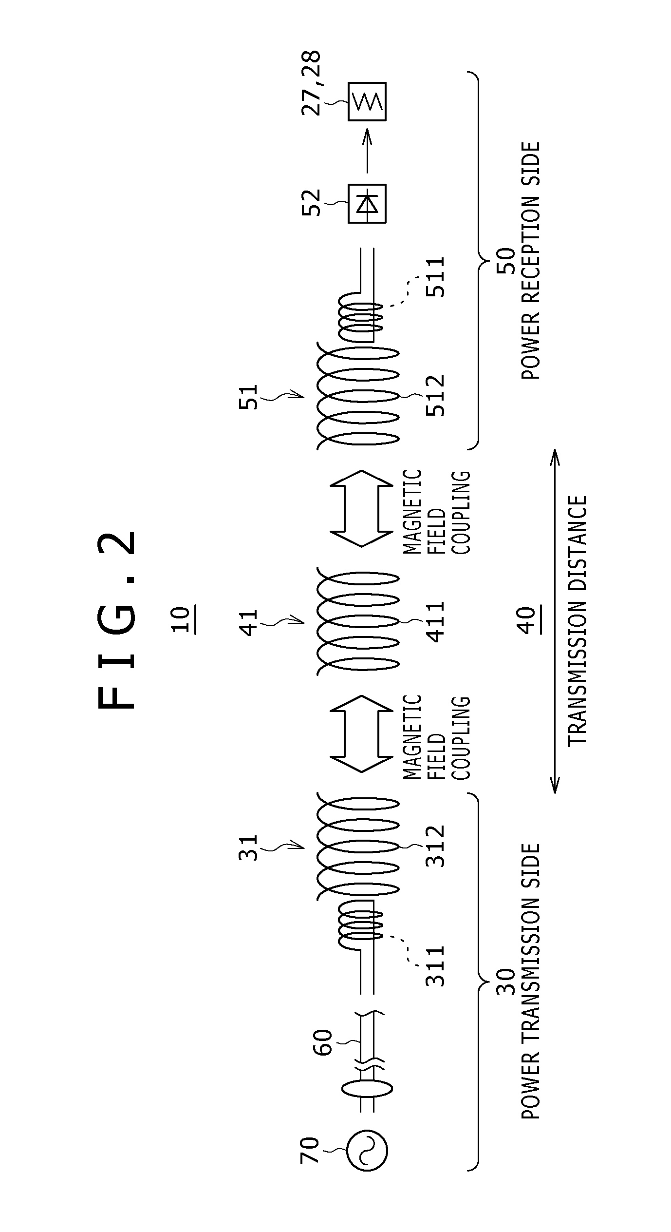
Disclosed herein is a wireless power supplying rack, including: a power transmission device adapted to transmit power to be supplied; a repeater device adapted to repeat the transmission power of the power transmission device; a power reception device adapted to receive the power repeated by the repeater device; and a main body in which a load to which the power received at least by the power reception device from between the power reception device and the repeater device is supplied is disposed; at least the repeater device and the power reception device from among the power transmission device, repeater device and power reception device being incorporated in the main body; wherein the power transmission device, the repeater device and the reception device have a first resonance element, a second resonance element and a third resonance element, respectively.
Description
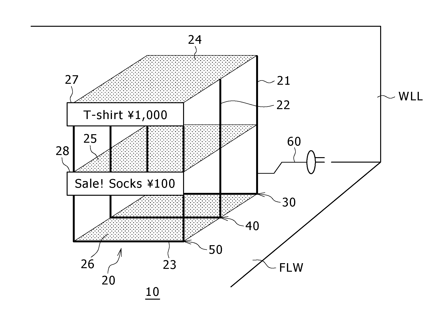
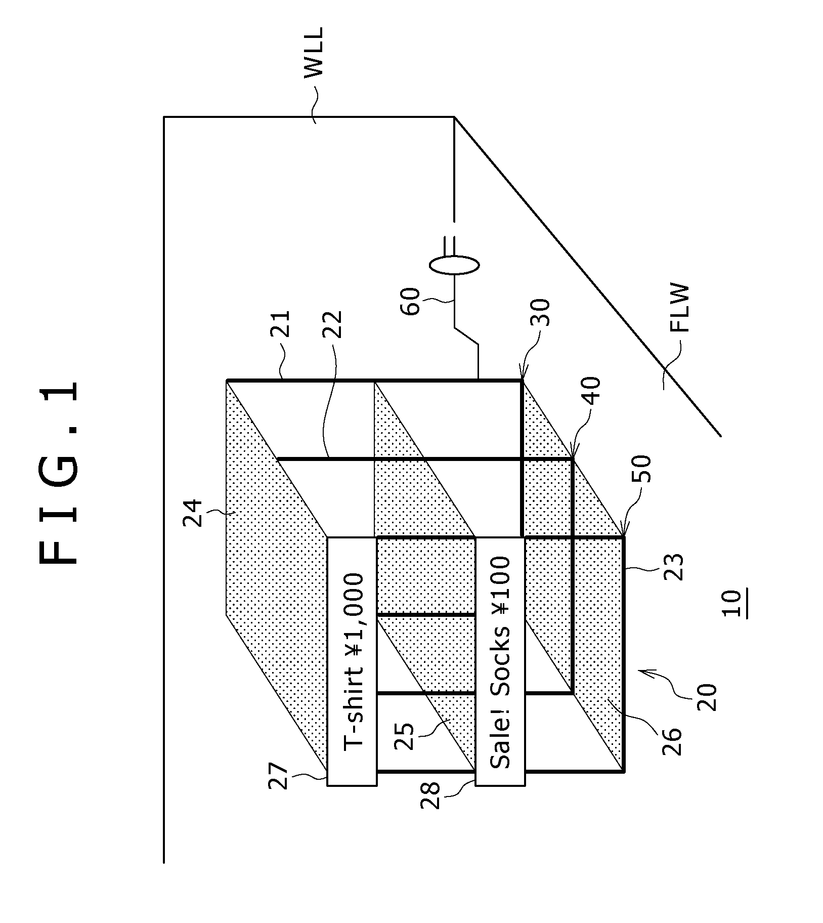
BACKGROUND OF THE INVENTION[0001]1. Field of the Invention[0002]This invention relates to a wireless power supplying rack of the contactless power supplying type which can supply power in a contactless or wireless fashion to a load such as a lighting fixture or a display device on a display rack or the like.[0003]2. Description of the Related Art[0004]For example, a technique for supplying power to a display device on a commodity rack is disclosed in Japanese Patent Laid-Open No. 2008-305737 (hereinafter referred to as Patent Document 1).[0005]In the technique disclosed in Patent Document 1, a rail of a DC power supply is embedded in a front face portion of a rack, and an attachment having a contact for establishing continuity with the rail is fitted with the rail to allow power supply to the attachment.SUMMARY OF THE INVENTION[0006]However, according to the technique of Patent Document 1 described above, basically a cable is used for power supply to any other member than the power ...
Claims
Login to View More Application Information
Patent Timeline
 Patent Type & Authority Patents(United States)
IPC IPC(8): H01F37/00A47F5/00H04B5/48
CPCH04B5/0093H01Q7/00H04B5/0037H02J5/005H02J50/50H02J50/12H04B5/266H04B5/79
Inventor KOZAKAI, OSAMU
Owner SONY CORP
Features
- R&D
- Intellectual Property
- Life Sciences
- Materials
- Tech Scout
- Unparalleled Data Quality
- Higher Quality Content
- 60% Fewer Hallucinations
Learn More Browse by: Latest US Patents, China's latest patents, Technical Efficacy Thesaurus, Application Domain, Technology Topic, Popular Technical Reports.
© 2025 PatSnap. All rights reserved.Legal|Privacy policy|Modern Slavery Act Transparency Statement|Sitemap|About US| Contact US: help@patsnap.com


