Wireless power supplying rack
a power supply rack and wireless technology, applied in the direction of transformers, inductances, show shelves, etc., can solve the problems of low design property and convenience, high cost, and high cost, and achieve high design property and convenience. high, high power supply efficiency
- Summary
- Abstract
- Description
- Claims
- Application Information
AI Technical Summary
Benefits of technology
Problems solved by technology
Method used
Image
Examples
first embodiment
1. First Embodiment
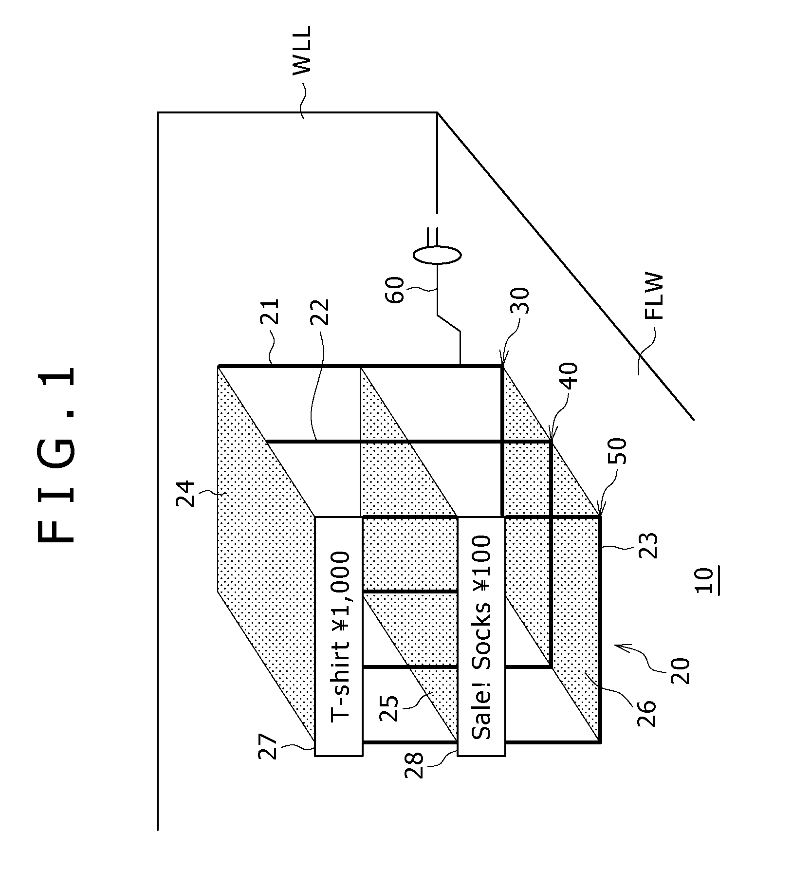
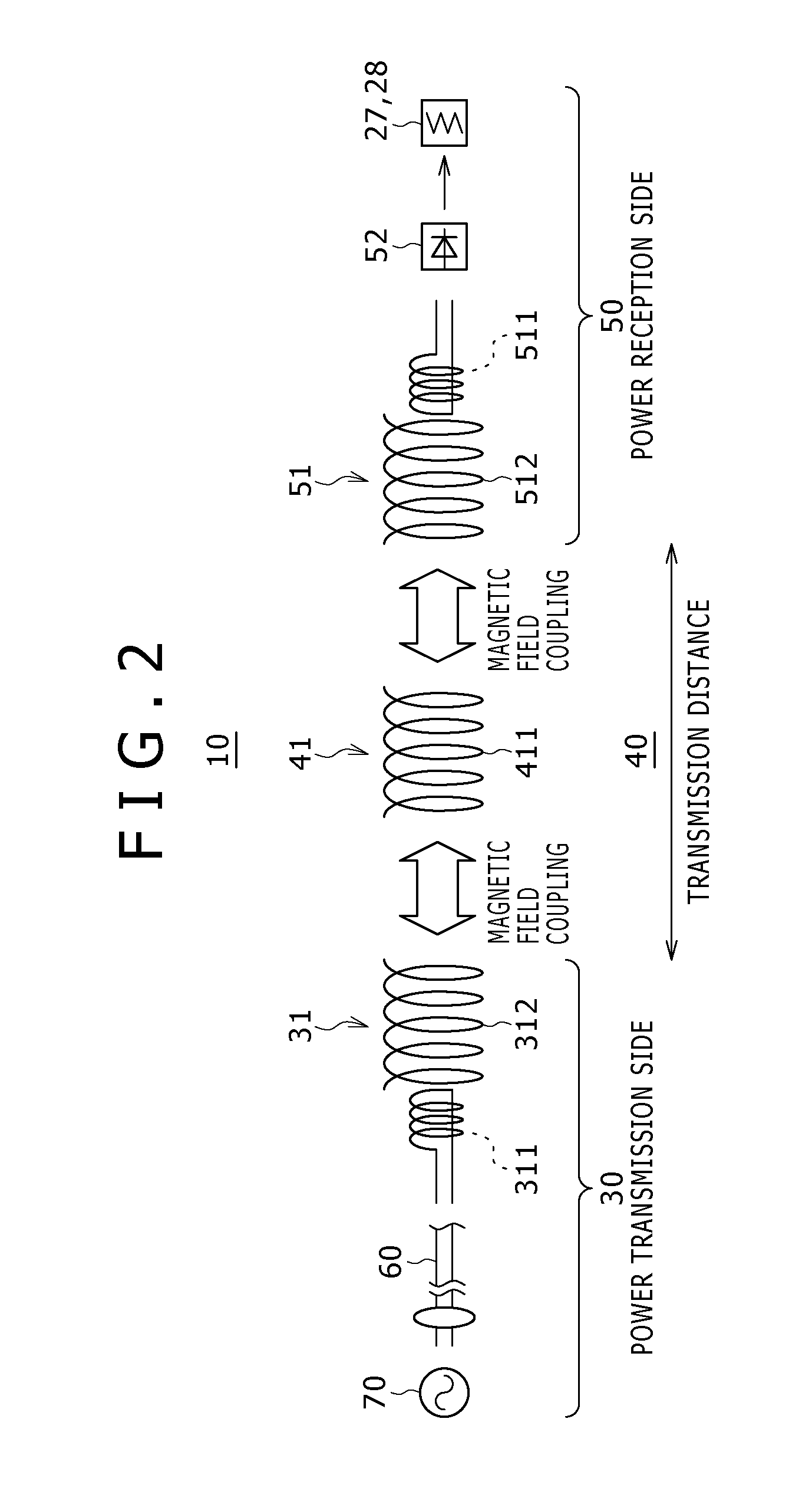
[0042]FIG. 1 shows an example of a configuration of a wireless power supply rack according to a first embodiment of the present invention, and FIG. 2 shows equivalent blocks of the wireless power supply rack.
[0043]Referring to FIGS. 1 and 2, the wireless power supplying rack 10 shown includes a rack main body 20, a power transmission device 30, a repeater device 40 and a power reception device 50.
[0044]In the wireless power supplying rack 10 according to the present first embodiment, the power transmission device 30, repeater device 40 and power reception device 50 are incorporated in frames which configure the skeleton of the rack main body 20 itself as hereinafter described in detail.
[0045]The rack main body 20 includes a first frame 21, a second frame 22 and a third frame 23 disposed in a predetermined spaced relationship from each other so as to form a skeleton.
[0046]The first frame 21, second frame 22 and third frame 23 are non-cut loop-shaped framework membe...
second embodiment
2. Second Embodiment
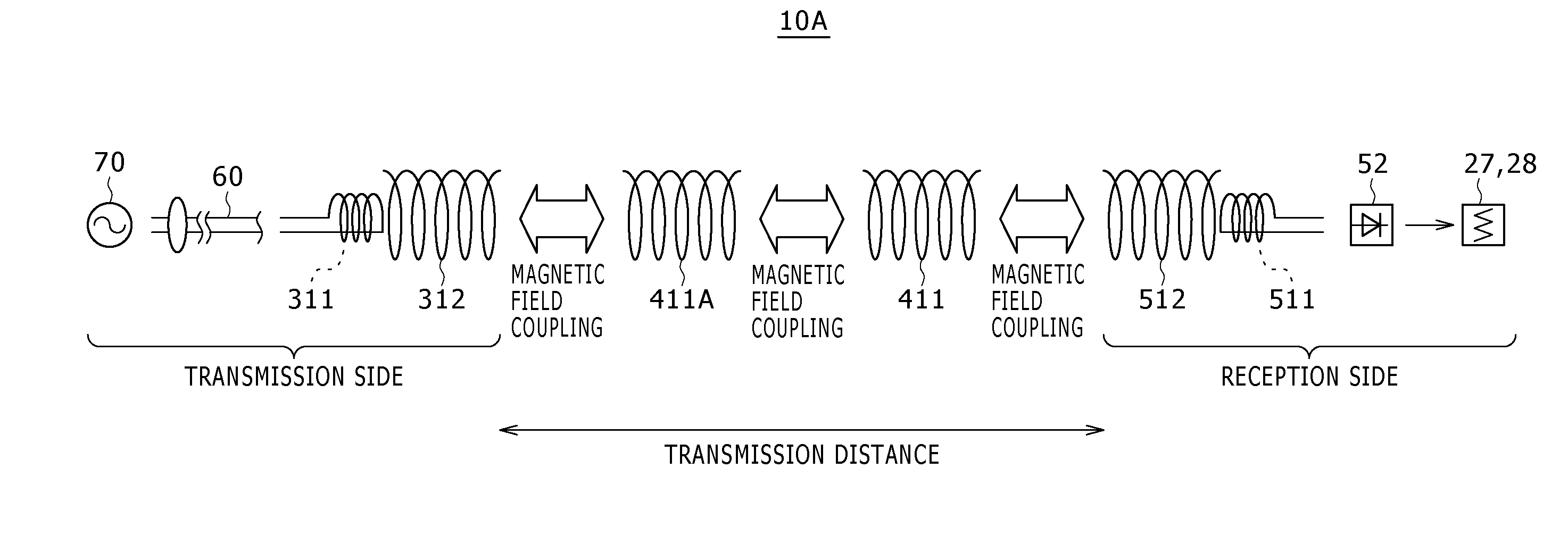
[0126]FIG. 9 shows an example of a configuration of a wireless power supplying rack according to a second embodiment of the present invention, and FIG. 10 shows equivalent blocks of the wireless power supply rack of FIG. 9.
[0127]Referring to FIGS. 9 and 10, the wireless power supplying rack 10A according to the present second embodiment is similar to but different from the wireless power supplying rack 10 according to the first embodiment in that a repeating device 40-2 is incorporated in the first frame 21 in place of the power transmission device 30.
[0128]Further, in the present second embodiment, the first frame 21 on which the power transmission device 30A is mounted is formed as a non-skeleton frame 21A disposed outside the main body 20A.
[0129]The non-skeleton frame 21A is embedded, for example, in the wall face WLL.
[0130]In this instance, in order to obtain a high power supply efficiency, the main body 20A is disposed such that the resonance coil 312 of the...
third embodiment
3. Third Embodiment
[0132]FIG. 11 shows an example of a configuration of a wireless power supplying rack according to a third embodiment of the present invention.
[0133]Referring to FIG. 11, the wireless power supplying rack 10B according to the present third embodiment is similar to but different from the wireless power supplying rack 10A according to the second embodiment in that the non-skeleton frame 21B is embedded not in the wall face WLL but in the floor face FLW.
[0134]Further, the first frame 21, second frame 22 and third frame 23 are disposed in a predetermined spaced relationship in order from the floor face FLW toward the top plate side such that they are opposed to the loop portion of the non-skeleton frame 21B.
[0135]Also in this instance, the display rack comes to require no power supply cable and is designed so clear-cut that it can be assembled and disassembled readily.
[0136]As described above, according to the present embodiment, the following advantages can be achieve...
PUM
 Abstract
Description
Claims
Application Information
 - R&D
- Intellectual Property
- Life Sciences
- Materials
- Tech Scout
- Unparalleled Data Quality
- Higher Quality Content
- 60% Fewer Hallucinations
Browse by: Latest US Patents, China's latest patents, Technical Efficacy Thesaurus, Application Domain, Technology Topic, Popular Technical Reports.
© 2025 PatSnap. All rights reserved.Legal|Privacy policy|Modern Slavery Act Transparency Statement|Sitemap|About US| Contact US: help@patsnap.com


