Coal-fired power generation system based on bypass flue at tail part of boiler

A bypass flue, thermal power generation technology, used in steam generation, machines/engines, lighting and heating equipment, etc., can solve the problems of expensive, small exhaust gas volume, low temperature corrosion, etc., to solve serious low temperature Corrosion, improved power supply efficiency, and the effect of avoiding severe corrosion

Inactive Publication Date: 2015-12-16
UNIV OF SHANGHAI FOR SCI & TECH
View PDF6 Cites 15 Cited by
  • Summary
  • Abstract
  • Description
  • Claims
  • Application Information

AI Technical Summary

Problems solved by technology

The outstanding problems of this air preheating scheme are: the heat exchange temperature difference between the flue gas and the air in the first stage air preheater is very small, resulting in a large equipment volume and investment cost of the low temperature air preheater; After the low-temperature flue gas preheating air, the air temperature rise that can be obtained is small, so that the amount of flue gas that can enter the bypass flue for exhaustion and extraction is small, so the coal-saving benefits of the unit are relatively limited; moreover, the more prominent problem Yes, because the temperature of the tube wall on the heating surface is very low, the heating surface of the low-temperature air preheater inevitably faces severe low-temperature corrosion. Therefore, the heating surface of the low-temperature air preheater must be made of very expensive corrosion-resistant materials, which seriously reduces The engineering feasibility and investment economy of the bypass flue scheme

Method used


Image

  • Coal-fired power generation system based on bypass flue at tail part of boiler
  • Coal-fired power generation system based on bypass flue at tail part of boiler
  • Coal-fired power generation system based on bypass flue at tail part of boiler

Examples


Embodiment Construction

[0018] In order to make the technical means, creative features, goals and effects of the present invention easy to understand, the following embodiments describe in detail the thermal power generation system based on the bypass flue at the boiler tail in conjunction with the accompanying drawings and embodiments.

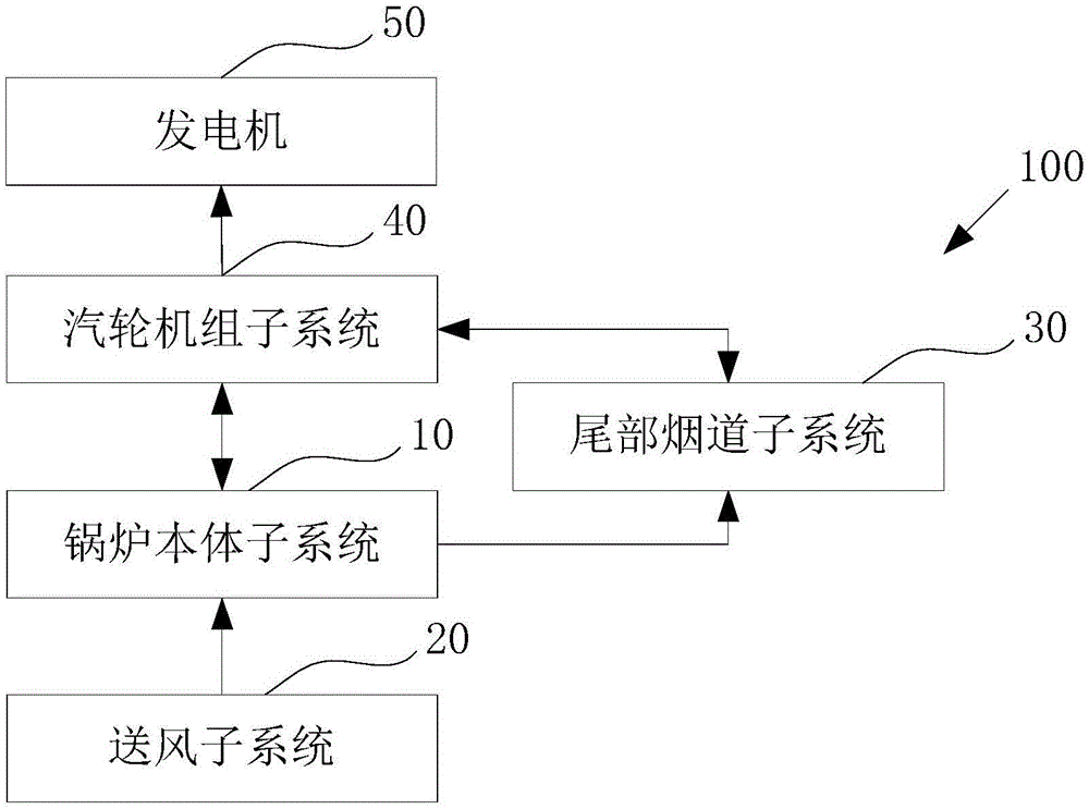
[0019] figure 1 It is a structural block diagram of a thermal power generation system based on a boiler tail bypass flue in an embodiment of the present invention.

[0020] Such as figure 1 As shown, the thermal power generation system 100 based on the bypass flue at the boiler tail uses the heat generated by fuel combustion to generate electricity, which can not only reduce high-pressure steam extraction to improve power generation efficiency, but also avoid the heat exchange caused by low-temperature flue gas preheating air. Corrosion of thermal equipment, thermal power generation system 100 based on boiler tail bypass flue includes: boiler body subsystem 10 , ai...


PUM


Abstract

The invention provides a coal-fired power generation system based on a bypass flue at the tail part of a boiler as well as warm air obtained through steam extraction. The coal-fired power generation system adopts fuel to heat feed water so as to generate power, and is characterized by comprising a boiler body subsystem, an air supply subsystem, a tail flue subsystem, a turboset subsystem and a generator, wherein the boiler body subsystem comprises the boiler and a boiler flue, the boiler is provided with a hearth, and the boiler flue is connected with an outlet of the hearth and divided into a main flue and the bypass flue; the air supply subsystem comprises an air feeder, a front air preheater and a flue air preheater, the air feeder is used for supplying environment cold air, the front air preheater is connected with the air feeder and used for preheating the environment cold air to obtain warm air, and the flue air preheater is arranged in the main flue and used for heating the warm air; the tail flue subsystem comprises a high-pressure feed water heat exchanger and a low-pressure condensed water heat exchanger, the high-pressure feed water heat exchanger is arranged in the bypass flue and close to an inlet of the bypass flue, and the low-pressure condensed water heat exchanger is arranged in the bypass flue and close to an outlet of the bypass flue.

Description

technical field [0001] The invention belongs to the field of thermal power generation, in particular to a thermal power generation system based on a boiler tail bypass flue. Background technique [0002] With the continuous rise of energy prices and the increasingly stringent requirements for energy conservation and emission reduction, the utilization of waste heat from power station boiler flue gas has been widely valued. At present, the most widely used flue gas waste heat recovery method is to install a heat exchanger (generally called a low-pressure economizer) in the boiler exhaust flue after the air preheater, and use the low-temperature waste heat of the boiler exhaust to heat the steam turbine condensate , so that part of steam turbine extraction can be saved, and the purpose of increasing unit output and reducing power supply coal consumption can be achieved. The shortcomings of this method are: the temperature of the boiler exhaust gas is low, resulting in a low h...

Claims


Application Information

Patent Timeline
Patent Type & Authority Applications(China)
IPC IPC(8): F22D1/36F01K11/02F01K17/02
Inventor 马有福杨丽娟岳荣
Owner UNIV OF SHANGHAI FOR SCI & TECH
Why Eureka
Try Eureka