
Reactive compensation configuration method based on reactive voltage feature for wind power 500kV collecting transformer substation

A technology of wind power collection and voltage characteristics, applied in reactive power adjustment/elimination/compensation, reactive power compensation, wind power generation, etc. question

Active Publication Date: 2014-04-23
STATE GRID CORP OF CHINA +4
View PDF3 Cites 15 Cited by
  • Summary
  • Abstract
  • Description
  • Claims
  • Application Information

AI Technical Summary

Problems solved by technology

When the wind farm is at the end of the power grid, the voltage support is weak, and after the system fails, the voltage of the wind farm may drop severely, and a large number of wind turbines will be disconnected from the grid due to low voltage; Imperfect, unable to perform automatic voltage adjustment in time, and the reactive power compensation device that supports the system voltage and reactive power loss input is still in the state of input when the wind power is generated in the wind power collection station, and a large number of surplus capacitive reactive power compensation devices are still running on the grid. The system voltage is greatly increased, causing a large number of fans to go off the grid due to overvoltage

Method used


Image

  • Reactive compensation configuration method based on reactive voltage feature for wind power 500kV collecting transformer substation
  • Reactive compensation configuration method based on reactive voltage feature for wind power 500kV collecting transformer substation
  • Reactive compensation configuration method based on reactive voltage feature for wind power 500kV collecting transformer substation

Examples


Embodiment Construction

[0058] The specific embodiments of the present invention will be further described in detail below in conjunction with the accompanying drawings.

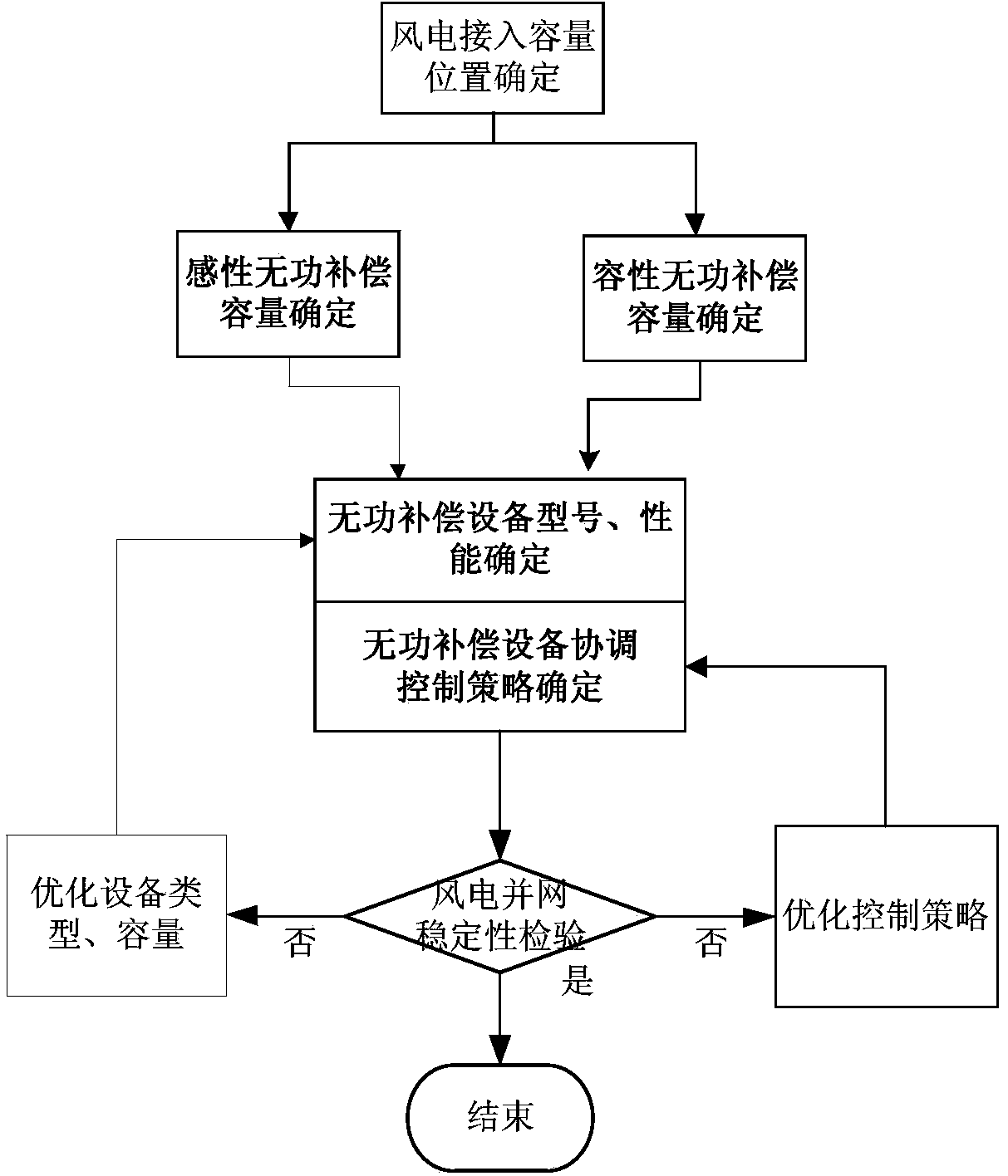
[0059] Such as figure 1 as shown, figure 1 It is a flowchart of a reactive power compensation configuration method for a wind power 500kV collection substation based on reactive voltage characteristics; the reactive power compensation configuration method for a wind power 500kV collection substation based on reactive voltage characteristics of the present invention includes the following steps:

[0060] Step 1. Determine the access capacity and access location of wind power to the grid;

[0061] Step 2. Determine the inductive reactive power compensation capacity and capacitive reactive power compensation capacity required by the power grid;

[0062] Step 3. Determine the type and capacity of reactive power compensation equipment;

[0063] Step 4. Determine the coordinated control strategy for reactive power compensation equipme...


PUM


Abstract

The invention provides a reactive compensation configuration method based on a reactive voltage feature for a wind power 500kV collecting transformer substation. The method comprises the following steps: determining the access capacity and access position of wind power accessing a power grid; determining inductive reactive compensation capacity and capacitive reactive compensation capacity needed by the power grid; determining the type and the capacity of reactive compensation equipment; determining a coordination control strategy of the reactive compensation equipment; detecting the stability of a wind power grid-connected system. By adopting the method, a reactive compensation configuration scheme is determined for the 500kV collecting transformer substation, so that a technical line is provide for the reactive compensation configuration scheme of the 500kV collecting transformer substation after the wind power accesses the power grid, and stable running after wind power grid connection is ensured.

Description

technical field [0001] The present invention relates to a method in the technical field of grid connection of wind turbines in new energy power generation technology, in particular to a reactive power compensation configuration method for a wind power 500kV collection substation based on reactive power voltage characteristics. Background technique [0002] Wind power is clean and renewable energy, and vigorously developing renewable energy is necessary to rationally adjust the power structure and is an important part of the energy development strategy. The development and utilization of renewable energy is a major measure to promote environmental protection, improve energy structure, and maintain sustainable social and economic development. Renewable energy power generation including wind power generation, biomass power generation, and solar photovoltaic power generation has developed rapidly in recent years. Among them, wind power is one of the new energy power generation ...

Claims


Application Information

Patent Timeline
Patent Type & Authority Applications(China)
IPC IPC(8): H02J3/18H02J3/38
CPCY02E10/76Y02E40/30
Inventor 李琰王真迟永宁苏媛媛田新首刘超孙蔚曹伟雷为民谷冰王信赵爽罗玮魏林君张占奎汤海雁王志冰曲春辉仇卫东胡君慧
Owner STATE GRID CORP OF CHINA
Learn More