Linear actuator

Active Publication Date: 2014-04-22
FILTRONIC WIRELESS
14 Cites 4 Cited by

AI-Extracted Technical Summary

Problems solved by technology

Simple linear actuators wherein the components are coupled together by threads tend to suffer from a degree of backla...

Method used

[0075]The design of the two threads 10,11 of the linear actuator 1 according to the invention prevents backlash when the direction of rotation of the drive arm 2 is reversed. One embodiment of the threads 10,11 is shown in cross section in FIG. 3. Each thread 10,11 can be arranged on either drive arm 2 or extension arm 3.
[0077]An important consideration is wear on the threads during use. With known threads, as the ridges are worn. away the ridge of one thread becomes an increasingly poor fit in the groove of the other. The degree of backlash therefore increases. With the threads 10,11 according to the invention the ridge 14 of one thread 11 will always abut both sides 20,21 of the groove 15 of the other e...

Benefits of technology

[0015]The linear actuator according to the invention is a simple mechanical device but does not suffer from backlash. The device is therefore suitable for use in applications where backlash...

Abstract

A linear actuator includes a drive arm and an extension arm each extending along a common drive axis. One of the arms has a plurality of resiliently deformable fingers extending beyond the end of the arm towards the other arm. At least one of the fingers has a thread on its inner face while the other arm has a threaded portion. At least part of the threaded portion is received between the fingers. The fingers are adapted to urge the threads of the two arms into interengagement such that rotation of the drive arm about the drive axis displaces the extension arm along the drive axis. The two threads are arranged such that when the ridge of one thread is received in the groove of the other thread the two sides of the ridge abut the two edges of the mouth of the groove.

Application Domain

NutsPortable lifting +4

Technology Topic

Linear actuatorRidge +2

Image

  • Linear actuator
  • Linear actuator
  • Linear actuator

Examples

  • Experimental program(1)

Example

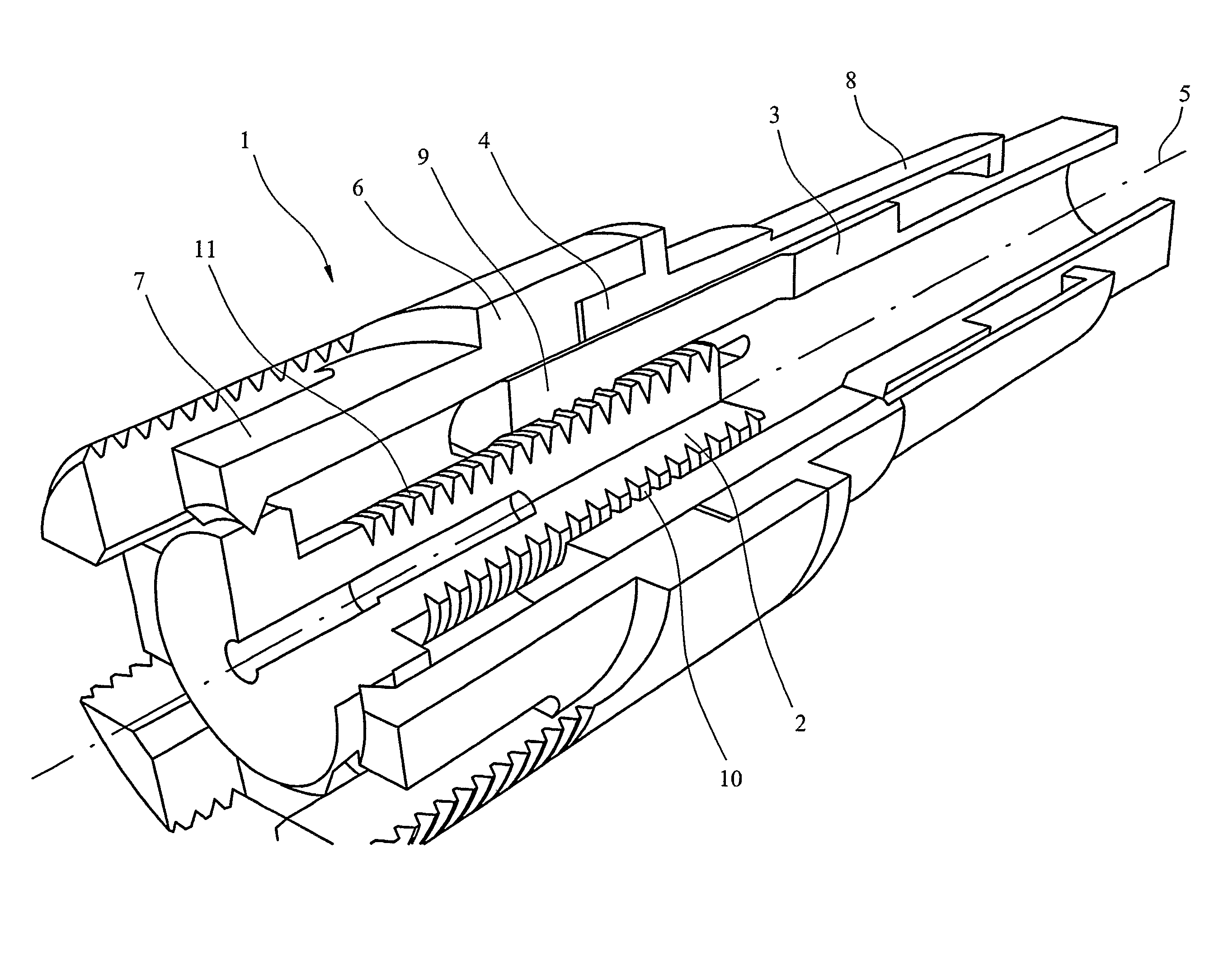
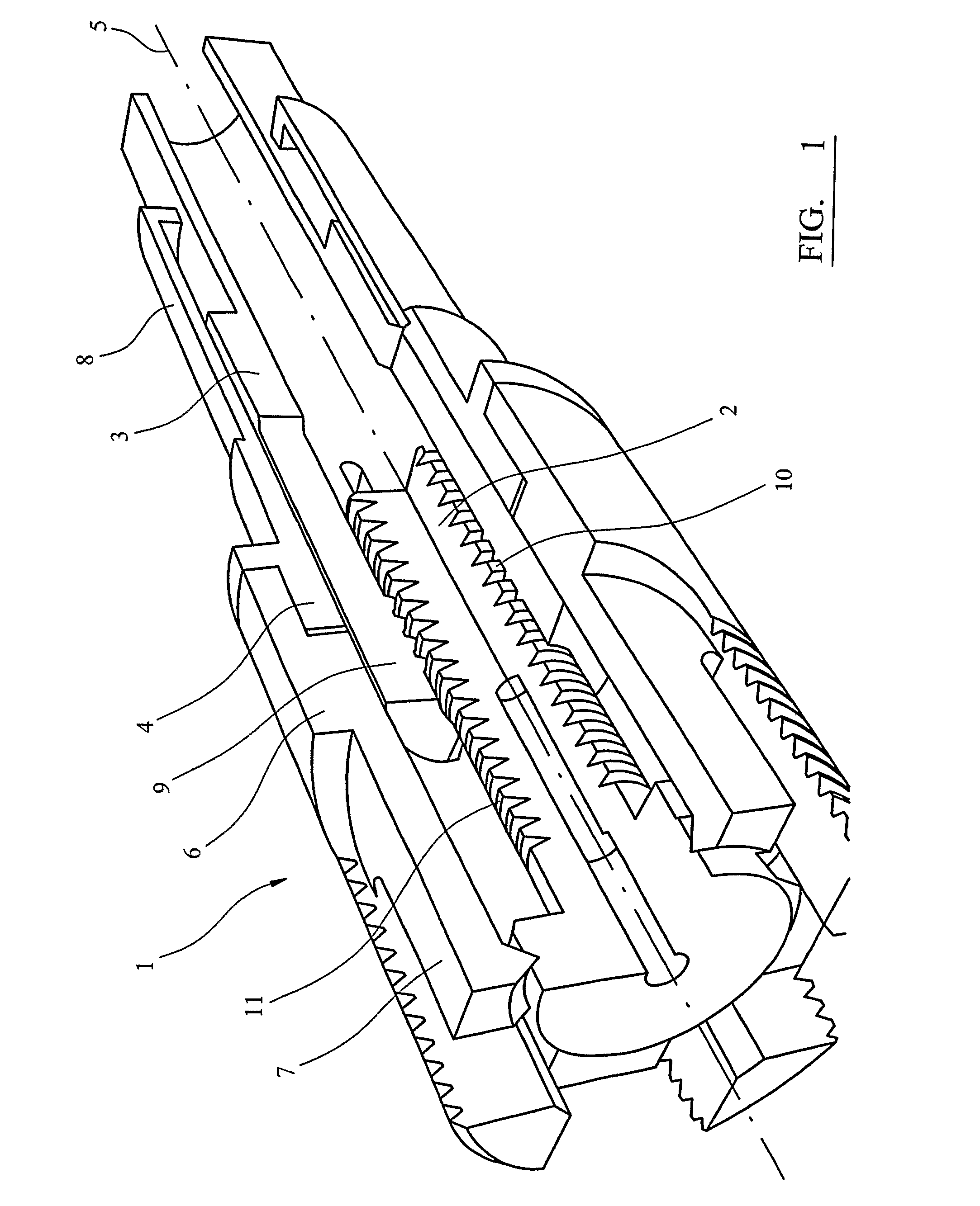
[0069]Shown in FIG. 1 is a linear actuator 1 according to the invention. The linear actuator 1 comprises a drive arm 2 and an extension arm 3 both partially received within a housing 4. The drive arm 2 and extension arm 3 both extend along a common drive axis 5.
[0070]The housing 4 comprises a housing body 6. A plurality of holding fingers 7 extend from the housing body 6 and grip the drive arm 2 therebetween. The holding fingers 7 constrain the drive arm 2 such that it is free to rotate about the drive axis 5 but cannot be displaced along the drive axis 5. The holding fingers 7 are described in more detail below. Similarly, a plurality of gripping fingers 8 extend from the housing body 6 and grip the extension arm 3 therebetween. The gripping fingers 8 constrain the extension arm 3 such that it is free to be displaced along the drive axis 5 but resist rotation of the extension arm 3 about the drive axis 5. Again the gripping fingers 8 are described in more detail below.
[0071]The end of the extension arm 3 is split into a plurality of independent resiliently deformable fingers 9 which extend beyond the end of the arm 3 towards the drive arm 2. In this embodiment the fingers 9 are substantially parallel to the drive axis 5. A thread 10 is arranged on the inner faces of the fingers 9.
[0072]The drive arm 2 has a threaded portion 11 on its outer face. The threaded portion 11 of the drive arm 2 is received within the fingers 9 such that the two threads 10,11 interengage. The drive arm 2 is dimensioned such that the fingers 9 are deformed outwardly away from the drive axis 5. The fingers 9 therefore urge the two threads 10,11 into interengagement. The fingers 9 are adapted such that the force applied by the fingers 9 urging the two threads 10,11 together is substantially normal to the drive axis 5.
[0073]Because of the threaded engagement between the drive arm 2 and the extension arm 3 rotation of the drive arm 2 about the drive axis 5 displaces the extension arm 3 along the drive axis 5.
[0074]FIGS. 2(a) and 2(b) show in cross section a drive arm 2 and extension arm 3 interengaged by two standard threads 12,13. The ridges of one thread 12 do not fit exactly within the grooves of the other thread 13. Accordingly, when the drive arm thread 12 is being rotated in a first direction (FIG. 2(a)) the ridges of the drive arm thread 12 abut the right hand wall of the extension arm groove pushing the extension arm 3 to the right along the drive axis 5. When the direction of rotation of the drive arm 2 is reversed the drive arm thread 12 shifts position slightly with respect to the extension arm thread 13 so that it abuts the left hand groove wall of the extension arm thread 13 (FIG. 2(b)). The drive arm thread 12 then drives the extension arm 3 to the left along the drive axis 5. This slight shift in position before the threads 12,13 engage causes backlash.
[0075]The design of the two threads 10,11 of the linear actuator 1 according to the invention prevents backlash when the direction of rotation of the drive arm 2 is reversed. One embodiment of the threads 10,11 is shown in cross section in FIG. 3. Each thread 10,11 can be arranged on either drive arm 2 or extension arm 3.
[0076]As can be seen, as the ridge 14 of one thread 11 is urged into the groove 15 of the other thread 10 by the fingers 9 each of the two sides 16,17 of the ridge 14 abuts a corresponding edge 18,19 of the mouth of groove 15. The angle between the ridge faces 16,17 at the points of abutment is greater than the angle between the groove faces 20,21 at the point of abutment. Because the ridge 14 is in contact with both edges 18,19 of the mouth of the receiving groove 15 there is no change in relative position of drive arm thread 11 and extension arm thread 10 when the direction of rotation of the drive arm 2 is changed. Backlash is therefore eliminated.
[0077]An important consideration is wear on the threads during use. With known threads, as the ridges are worn. away the ridge of one thread becomes an increasingly poor fit in the groove of the other. The degree of backlash therefore increases. With the threads 10,11 according to the invention the ridge 14 of one thread 11 will always abut both sides 20,21 of the groove 15 of the other even as the threads 10,11 are worn away because of the fingers 9 urging the threads 10,11 into interengagement. This maintains zero backlash.
[0078]A further important feature of the threads 10,11 of the linear actuator 1 according to the invention is that the ridge 14 of one thread 11 contacts the mouth of the groove 15 along lines at the edges 18,19 of the mouth, rather than over an extended area as with known threads. Rotation of the drive arm 2 therefore mainly imparts a force along the drive axis 5 to the extension arm 3 and only imparts a very minimal rotational force to the extension arm 3 around the drive axis 5. The importance of this is described in more detail below.
[0079]Shown in FIG. 4 is a further embodiment of the threads 10,11 of a linear actuator 1 according to the invention shown in cross section. In this embodiment both threads 10,11 have V shaped ridges 14 and grooves 15. The ridge angle of one thread 11 (i.e. the angle between ridge faces 16,17 at the point of contact of the two) is wider than the groove angle (i.e. the angle between the groove faces 20,21 at the point of contact of the two) of the other thread 10 so ensuring that the ridge 14 abuts both sides 20,21 of the mouth of the groove 15.
[0080]Shown in FIG. 5 are the fingers 9 extending beyond the end of the extension arm 3. In this embodiment the extension arm 3 comprises four fingers 9 which are equally spaced about the drive axis 5. In alternative embodiments different numbers of fingers 9 are possible. In an alternative embodiment (not shown) the end comprises three fingers 9 equally spaced about the drive axis 5. In this embodiment two of the fingers 9 of the extension arm 3 extend beyond the others to form end stops 22. The end stops 22 are on opposite sides of the drive axis 5.
[0081]FIG. 6 shows the end of the drive arm 2 remote from the extension arm 3. The drive arm 2 comprises a threaded shaft portion 11 and a head portion 23. Extending from the head portion 23 parallel to the drive axis 5 are two end stops 24. Again the end stops 24 are arranged on opposite sides of the drive axis 5. As the drive arm 2 is rotated about the drive axis 5 the extension arm 3 travels along the drive arm. 2 towards the drive arm head portion 23. As the extension arm 3 reaches an end of its range of motion the extension arm end stops 22 rotate into abutment with the drive arm end stops 24 preventing further rotation of the drive arm 2 and travel of the extension arm 3. Because the end stops 22,24 are arranged in pairs, the abutment does not produce an overall lateral force on the extension arm 3 normal to the drive axis 5 so preventing displacement of the extension arm 3 to one side. In embodiments with an odd number of fingers 9 the end stops 22,24 are arranged such that as the fingers 9 rotate into abutment no overall lateral force is provided to the extension arm 3.
[0082]As can be seen in FIG. 6, the head portion 23 of the drive arm 2 includes a groove 25 extending around the drive arm 2. The function of this groove 25 is best explained with reference to FIG. 7 which shows the end of the drive arm 2 received within the housing 4. As mentioned above, resiliently deformable holding fingers 7 extend from the housing body 6 to the drive arm 2 and grip the head portion 23 therebetween. At the end of each arm 7 is a camming surface 26 (in this embodiment a ridge) which engages with a corresponding camming surface 27 of the head portion 23 (in this embodiment the groove). The ridge angle of the ridge 26 is wider than the groove angle of the groove 27 such that each side of the ridge 26 abuts a corresponding edge of the mouth of the groove 27. The drive arm 2 is therefore prevented from being displaced along the drive axis 5 but is free to rotate about the drive axis 5. Because the ridge 26 and groove 27 contact each other along lines along the edges of the mouth of the groove 27 there is very little friction opposing rotation of the drive arm 2.
[0083]In this embodiment the holding fingers 7 extend substantially parallel to the drive axis 5. The head portion 23 of the drive arm 2 bends the fingers 7 outwards so that the fingers 7 urge the ridge 26 into the groove 27. The urging force is substantially normal to the drive axis 5.
[0084]In an alternative embodiment of the invention the camming surface 27 of the drive arm 2 comprises a ridge and the camming surface 26 of the holding fingers 7 comprises a groove. The holding fingers 7 are adapted such that they can each be deformed independently of each other.
[0085]FIG. 8 shows the linear actuator 1 from the opposite end in cut away section. A plurality of gripping fingers 8 (in this case four fingers) extend from the housing body 6 and grip the extension arm 3 therebetween. The extension arm 3 of this embodiment is square in cross section at the point of gripping. The gripping fingers 8 each comprise a shaft 29 which extends substantially parallel to the drive axis 5. Each gripping finger 8 has a gripping head 30 which abuts the extension arm 3 and extends substantially normal to the drive axis 5. The extension arm 3 is dimensioned such that the gripping fingers 8 are bent outwards away from the drive axis 5 so urging the gripping heads 30 into abutment with the extension arm 3. The urging force is substantially normal to the drive axis 5.
[0086]Without any force applied to the extension arm 3 the gripping fingers 8 hold the extension arm 3 in an equilibrium orientation relative to the drive axis 5 as shown. If a rotational force is applied to the extension arm 3 about the drive axis 5 the gripping fingers 8 oppose rotation of the extension arm 3. This is because of the shape of the extension arm 3. As the extension arm 3 attempts to rotate; the extension arm 3 urges the gripping fingers 8 outwardly away from the drive axis 5. The gripping fingers 8 provide a restoring force returning the extension arm 3 to its equilibrium position.
[0087]If the rotational force is too great there is a danger the extension arm 3 will move from one equilibrium position to the next (in this case rotating by 90 degrees about the drive axis 5). As previously mentioned however the threads 10,11 which interengage the drive arm 2 and extension arm 3 are adapted such that the ridge of one abuts the mouth of the groove of the other along lines at the edge of the mouth. Rotating the drive arm 2 therefore produces relatively little turning force on the extension arm 3 about the drive axis 5 so preventing this from happening.
[0088]Other shapes of cross section of the extension arm 3 are possible. Most generally the cross section of the extension arm 3 at the point of gripping is non circular. The cross section of the extension arm 3 can be an n sided polygon with n greater than three, preferably triangular, rectangular or square. The housing 4 will have a corresponding number of gripping fingers 8, one for each side of the polygon. Preferably the gripping fingers 8 are equally spaced about the drive axis 5.
[0089]The gripping fingers 8 are adapted such that each gripping finger 8 can be resiliently deformed independently of the others.
[0090]A further advantage of the linear actuator 1 according to the invention is that both the drive arm 2 and extension arm 3 are suspended by fingers 7,8 extending from the housing body 6. Neither the drive arm 2 nor the extension arm 3 is rigidly fixed to the housing 4 at any point. The independently deformable fingers 7,8 allows for a small substantially conical displacement of the extension arm 3 relative to the drive axis 5. Similarly, the independently deformable gripping fingers 8 allow for a conical displacement of the extension arm 3 about the drive axis 5 relative to the housing. The drive arm 2 and the 30 extension arm 3 can therefore be slightly misaligned during use without the linear actuator 1 jamming. In known linear actuators if the drive arm urged out of alignment with the extension arm during use the actuator will jam.
[0091]In a further embodiment of the invention (not shown) the housing 4 comprises a slot. A 5 protrusion extends from the side of the extension arm 3 and is received in the slot so preventing rotation of the extension arm 3 about the drive axis 5.
[0092]A typical application of such a linear actuator 1 is in the tuning of microwave resonators. The linear actuator 1 displaces a tuning member within a microwave resonant cavity to tune the microwave resonant cavity. The tuning member can be a metal. The tuning member can be a dielectric. Typically the linear actuator 1 is arranged outside the cavity with the extension arm 3 extending into the cavity via an aperture in the cavity wall. When used in such applications the actuator 1 is manufactured from one or more plastics materials.
[0093]In the above embodiments the end of the extension arm 3 is split into fingers 8 which grip the drive arm 2. In alternative embodiments the drive arm 2 grips the extension arm 3.

PUM

no PUM

Description & Claims & Application Information

We can also present the details of the Description, Claims and Application information to help users get a comprehensive understanding of the technical details of the patent, such as background art, summary of invention, brief description of drawings, description of embodiments, and other original content. On the other hand, users can also determine the specific scope of protection of the technology through the list of claims; as well as understand the changes in the life cycle of the technology with the presentation of the patent timeline. Login to view more.

Similar technology patents

Curling iron cover

InactiveUS20050252521A1dependable in useinexpensive to manufacture
Owner:LEBLANC CHERRYLL A

Potentiometric sensor device

InactiveUS8016991B2high structural integrityinexpensive to manufacture
Owner:ROBERT BOSCH GMBH

High-pressure injector

Owner:LIEBHERR COMPONENTS DEGGENDORF GMBH

Classification and recommendation of technical efficacy words

  • inexpensive to manufacture

Disposable transducer seal

ActiveUS20050154313A1inexpensive to manufacturequickly and easily instal
Owner:SOLTA MEDICAL

Low cost safety lancet

ActiveUS20070185515A1inexpensive to manufactureeasily assemble together
Owner:FACET TECH LLC

Passive Entry System for Automotive Vehicle Doors

ActiveUS20090160211A1durable in constructioninexpensive to manufacture
Owner:FORD GLOBAL TECH LLC

Fiber optic cables and assemblies for fiber toward the subscriber applications

ActiveUS20110229098A1small cross sectioninexpensive to manufacture
Owner:CORNING OPTICAL COMM LLC
Why Eureka
Try Eureka