Supercharge Your Innovation With Domain-Expert AI Agents!

Fan unit assembly

a technology of fan unit and assembly, which is applied in the direction of lighting and heating apparatus, electrical apparatus casing/cabinet/drawer, instruments, etc., can solve the problems of inconvenient fastening operation, and achieve the effect of avoiding the complicated and inconvenient operation of fastening screws

Active Publication Date: 2014-04-22
INVENTEC CORP
View PDF17 Cites 5 Cited by
  • Summary
  • Abstract
  • Description
  • Claims
  • Application Information

AI Technical Summary

Benefits of technology

The invention is a fan unit assembly that is easy and quick to assemble. It uses handles on the front surface of the fan unit that can be rotated to guide the fan unit into position. The handles have pivoted on the side surfaces of the fan unit, and there are guiding parts on the fan unit's side surfaces and on partition boards. This makes it easy to smoothly guide the fan unit into place without having to fasten screws. The user can lock the handles in place to secure the fan unit. This design simplifies the assembly process and makes it more convenient for users.

Problems solved by technology

When an assembler fastens the screws, since sometime the thread holes are too close to the case, the operation space is limited which makes the fastening operation inconvenient.

Method used


Image

  • Fan unit assembly
  • Fan unit assembly
  • Fan unit assembly

Examples


Embodiment Construction

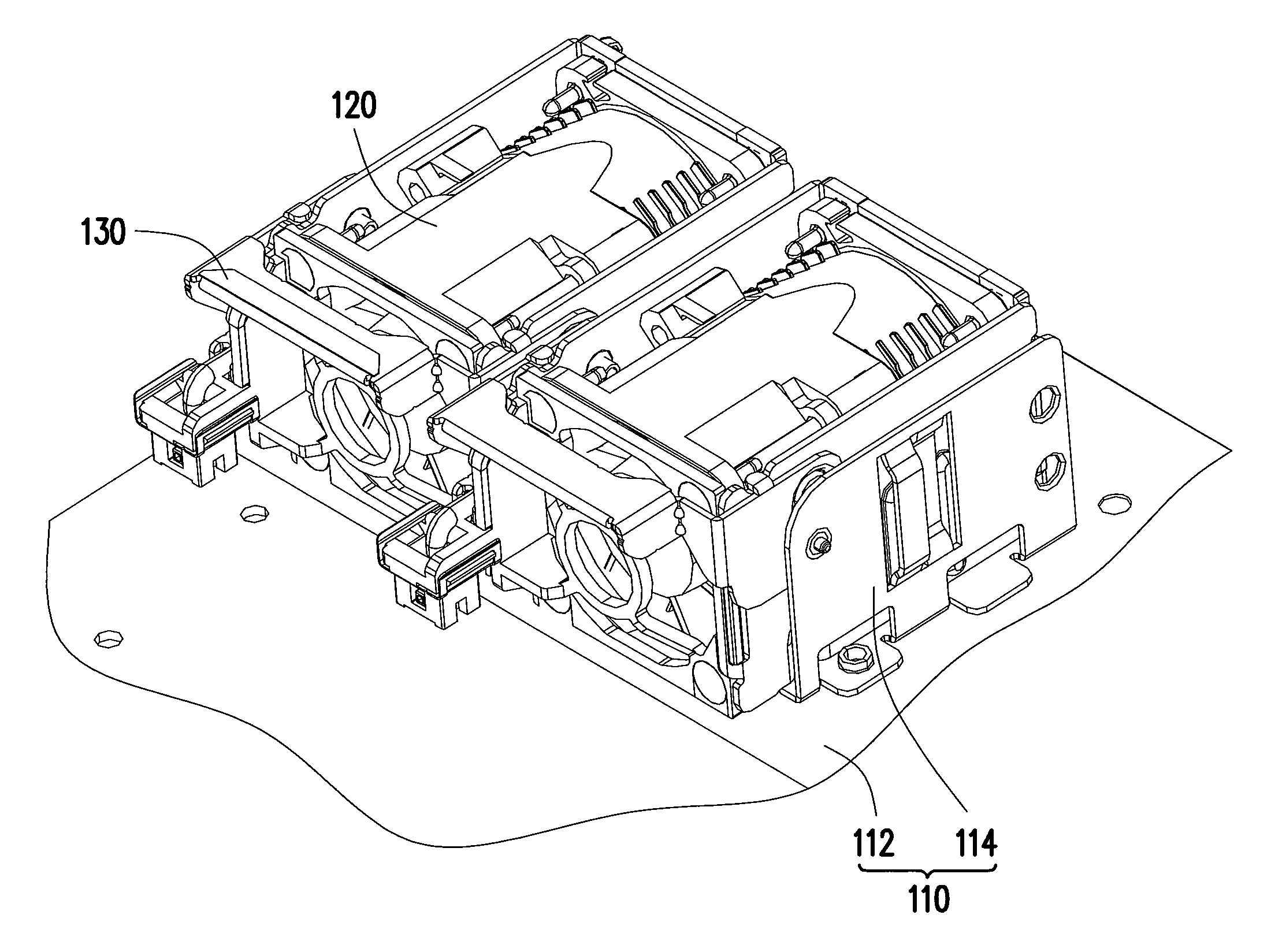
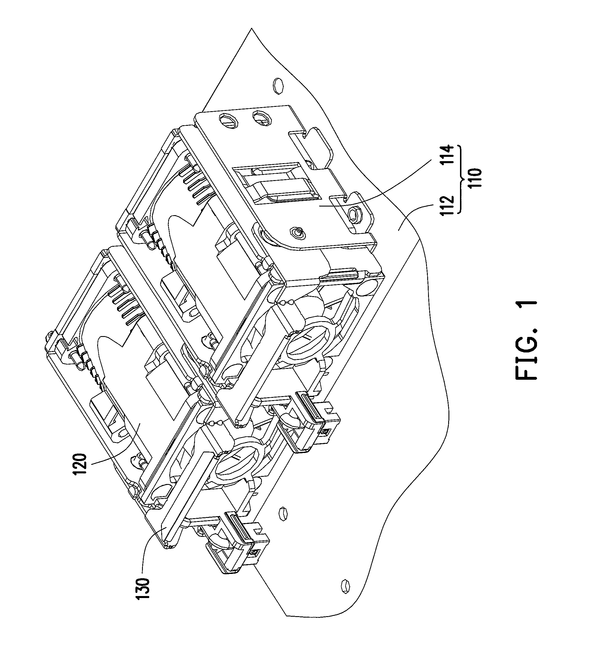
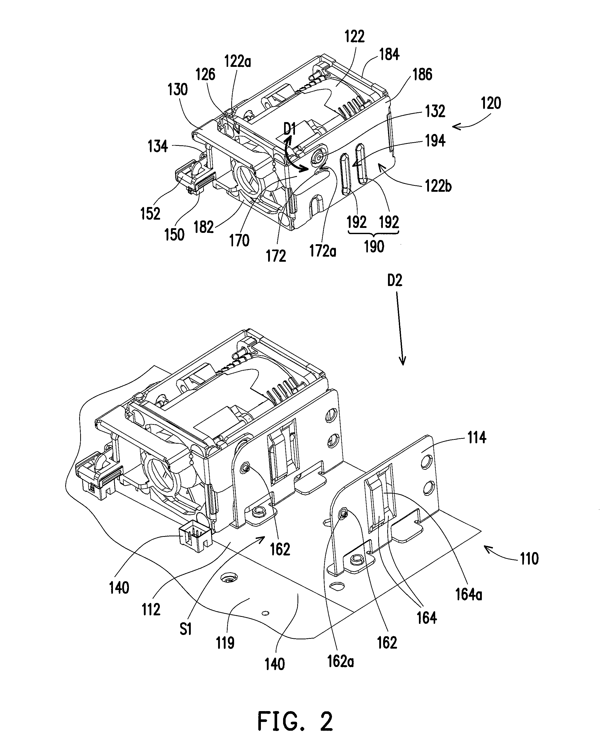
[0026]FIG. 1 is a schematic diagram of a fan unit assembly according to an embodiment of the invention and FIG. 2 is an assembly diagram of the fan unit assembly of FIG. 1. Referring to FIGS. 1 and 2, a fan unit assembly 10 of the embodiment is suitable for an electronic apparatus and includes a fan rack 110, a plurality of fan units 120 and a plurality of handles 130. The fan rack 110 includes a carrier 112 and a plurality of partition boards 114. The partition boards 114 are parallel to each other and erected on the carrier 112, and with the carrier 112 together define a plurality of fan-disposing regions S1. The fan units 120 are respectively disposed in the corresponding fan-disposing regions S1. Each of the partition boards 114 has a first positioning part 162 and at least one first guiding part 164 both facing towards the corresponding fan-disposing regions S1.

[0027]The fan units 120 are disposed in the fan-disposing regions S1 and respectively have a front surface 122a and tw...


PUM


Abstract

A fan unit assembly includes a fan rack, fan units and handles. The fan rack includes a carrier and parallel partition boards erected on the carrier to define fan-disposing regions. The partition board has at least one first positioning part and at least one first guiding part facing the corresponding fan-disposing region. The fan unit has two side surfaces and a front surface. The front surface connects the side surfaces. The side surfaces respectively have a second guiding part engaged with the first guiding part. The fan unit is suitable to move along the first guiding part through the second guiding part. The handles are disposed at the front surface and both ends thereof are bent to form two pivot portions respectively pivoted on the side surfaces. Each pivot portion has a second positioning part. When the handle rotates towards the front surface, the positioning parts interfere with each other.

Description

CROSS-REFERENCE TO RELATED APPLICATION[0001]This application claims the priority benefit of China application serial no. 201110267061.0, filed on Sep. 9, 2011. The entirety of the above-mentioned patent application is hereby incorporated by reference herein and made a part of this specification.BACKGROUND OF THE INVENTION[0002]1. Field of the Invention[0003]The invention generally relates to an assembly structure applied in fan units, and more particularly, to a fan unit assembly simply and fast assembled.[0004]2. Description of Related Art[0005]A server is a core computer serving many other computers in a network system and provides network users with required disks and service functions such as printing. Meanwhile, the server can provide the clients with sharing various resources in a network environment. The basic architecture of a server is roughly same as a common personal computer (PC) and is composed of a CPU, a memory and I / O equipments, and buses are used to interconnect th...

Claims


Application Information

Patent Timeline
Patent Type & Authority Patents(United States)
IPC IPC(8): H05K7/20
CPCG06F1/20
Inventor WANG, JIA-BINZHANG, GUI-JIAO
Owner INVENTEC CORP
Features
  • R&D
  • Intellectual Property
  • Life Sciences
  • Materials
  • Tech Scout
  • Unparalleled Data Quality
  • Higher Quality Content
  • 60% Fewer Hallucinations
Learn More