Implantable lead connector

a technology of lead connectors and connectors, which is applied in the direction of internal electrodes, therapy, heart stimulators, etc., can solve the problems of increasing the number of patients who require multiple devices to be implanted

Active Publication Date: 2014-04-22
IMPULSE DYNAMICS NV
View PDF23 Cites 18 Cited by
  • Summary
  • Abstract
  • Description
  • Claims
  • Application Information

AI Technical Summary

Problems solved by technology

As a result, there is a tendency to see an increasing number of patients require implant of multiple devices to address different therapeutic needs.

Method used


Image

  • Implantable lead connector
  • Implantable lead connector
  • Implantable lead connector

Examples


examples

[0160]Reference is now made to the following examples, which together with the above descriptions, illustrate some embodiments of the invention in a non limiting fashion.

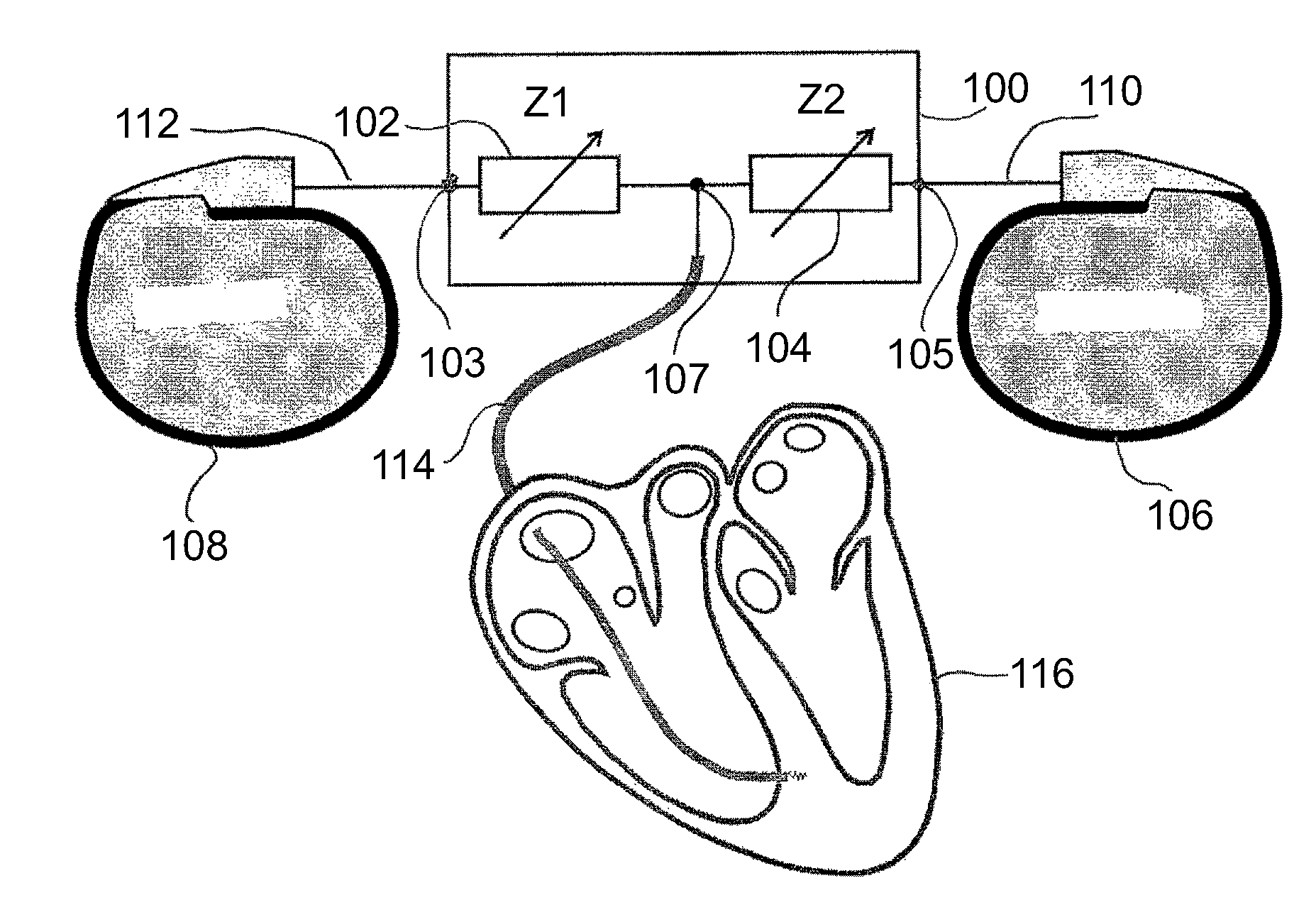
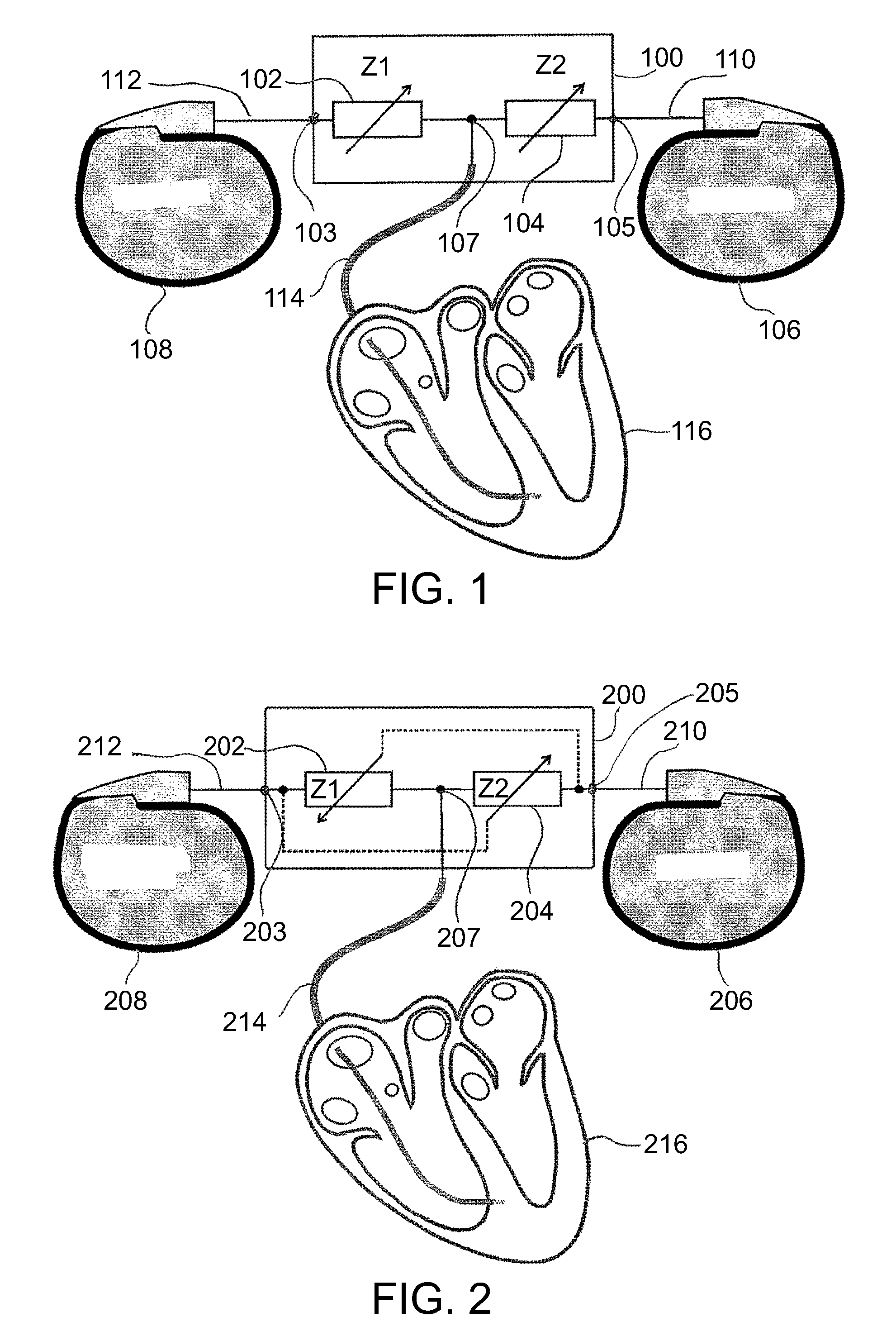
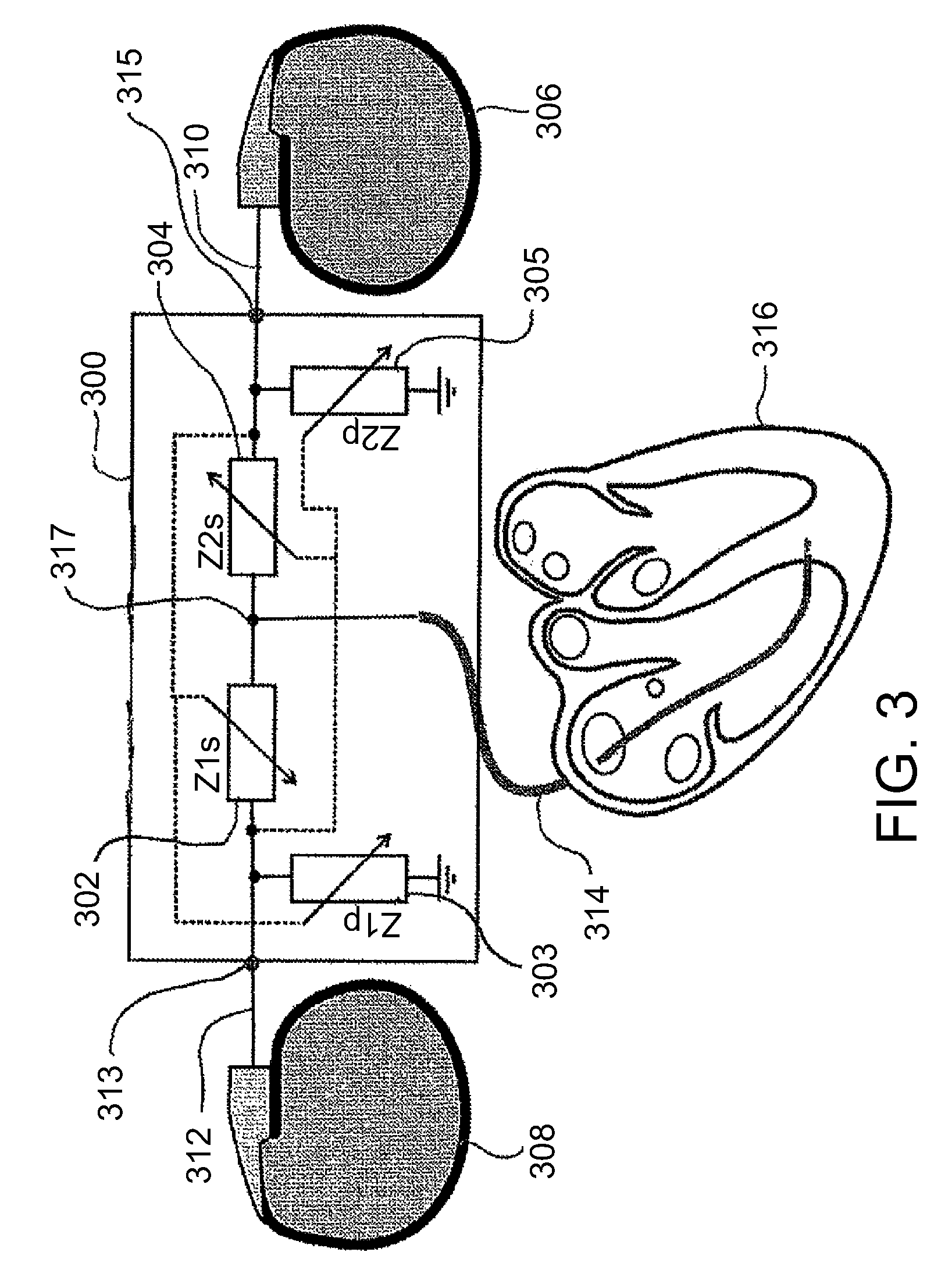
[0161]In an exemplary embodiment of the invention, the interconnection circuitry is integrated with an IPG (such as a contractility modulation device, for example as described in some of the above patents and applications). In one example, the circuitry is provided inside the casing of the IPG. In another example, the IPG includes a connector block and this block (e.g., of injected plastic) includes both connectors for attachment to an ICD or other device, such as pacemaker or combined CRT-ICD and connector(s) for one or more lead to the heart. Optionally the circuitry is also located within the connector block. In an exemplary embodiment of the invention the IPG and the interconnection circuitry are provided to a user for implantation as a monolithic inseparable device, in a sterile packaging, optionally with no sp...


PUM


Abstract

An implantable lead connector configured for long term implantation and to electrically interconnect multiple medical devices and to channel electrical signals between said interconnected devices and a target organ, comprising: a first port adapted to receive a first signal suitable to stimulate a target tissue, a second port adapted to receive a second signal suitable to stimulate a target tissue, and a third port configured to connect to a target organ, wherein at least one of said first and second ports is configured to connect to a signal generator not integrated with said connector.

Description

RELATED APPLICATION / S[0001]This application is a National Phase of PCT Patent Application No. PCT / IB2010 / 051783 having International filing date of Apr. 23, 2010, which claims the benefit of priority under 35 USC 119(e) of U.S. Provisional Patent Application No. 61 / 202,958 filed on Apr. 23, 2009 the disclosure of which is incorporated herein by reference in its entirety. The contents of the above applications are incorporated by reference as if fully set forth herein.FIELD AND BACKGROUND OF THE INVENTION[0002]The present invention, in some embodiments thereof, relates to active implantable medical devices and, more particularly, but not exclusively, to a device and a method for electrically interconnecting multiple active implantable medical devices[0003]Active implantable medical devices are commonly used to sense physiological signals from a target tissue or organ and frequently, in response, to deliver a therapy to the target tissue or organ in the form of electrical stimulation....

Claims


Application Information

Patent Timeline
Patent Type & Authority Patents(United States)
IPC IPC(8): A61N1/372A61N1/08
CPCA61N1/05A61N1/025A61N1/3752A61N1/362A61N1/39622A61N1/372A61N1/378A61N1/3785
Inventor ROUSSO, BENNYMIKA, YUVALBEN-HAIM, SHLOMOBURKHOFF, DANIELPRUTCHI, DAVID
Owner IMPULSE DYNAMICS NV
Why Eureka
Try Eureka