Apparatus, systems and methods for conditioning molten glass

a technology of apparatus and systems, applied in the field of apparatus, systems and methods for conditioning molten glass, can solve the problems of molten glass forming tendency to foam, rapid melting of glass batches, and large turbulen

Active Publication Date: 2014-04-29
JOHNS MANVILLE CORP
View PDF64 Cites 51 Cited by
  • Summary
  • Abstract
  • Description
  • Claims
  • Application Information

AI Technical Summary

Benefits of technology

[0013]one or more low momentum combustion burners positioned immediately downstream of each skimmer in either the roof, the sidewall structure, or both, and positioned to transfer heat to the molten mass of glass without substantial interference from the foamed material.
[0020]one or more low momentum combustion burners positioned immediately downstream of each skimmer in either the channel roof, the channel sidewall structure, or both, and positioned to transfer heat to the molten mass of glass without substantial interference from the foamed material.
[0026]e) operating the low momentum burners to route combustion products from the low momentum burners to transfer heat to the molten mass of glass without substantial interference from the foamed material.
[0033]f) operating the low momentum burners to route combustion products from the low momentum burners to transfer heat to the molten mass of glass without substantial interference from the foamed material.

Problems solved by technology

The introduction of high flow rates of oxidant and fuel into the molten glass, and the expansion of the gases cause rapid melting of the glass batch and much turbulence.
One drawback to submerged combustion is the tendency of the molten glass to foam.
The foam layer may impede the ability to apply heat to the glass using combustion burners to achieve or maintain temperature and compositional homogeneity of the molten glass, and may also impede the rate at which further bubbles in the melt rise and thus effect expulsion of the bubbles and mass flow rate of the melt in the channels.
In extreme cases, the foam generated may interfere with the traditional energy application methods employed, which may cause systems to require shutdown, maintenance and may result in a process upset.
Attempts to reduce the foam problem through process adjustments have not met with complete success in reducing foam to an acceptable amount.

Method used


Image

  • Apparatus, systems and methods for conditioning molten glass
  • Apparatus, systems and methods for conditioning molten glass
  • Apparatus, systems and methods for conditioning molten glass

Examples


Embodiment Construction

[0043]In the following description, numerous details are set forth to provide an understanding of the disclosed systems and methods. However, it will be understood by those skilled in the art that the systems and methods covered by the claims may be practiced without these details and that numerous variations or modifications from the specifically described embodiments may be possible and are deemed within the claims. All U.S. published patent applications and U.S. patents referenced herein are hereby explicitly incorporated herein by reference. In the event definitions of terms in the referenced patents and applications conflict with how those terms are defined in the present application, the definitions for those terms that are provided in the present application shall be deemed controlling.

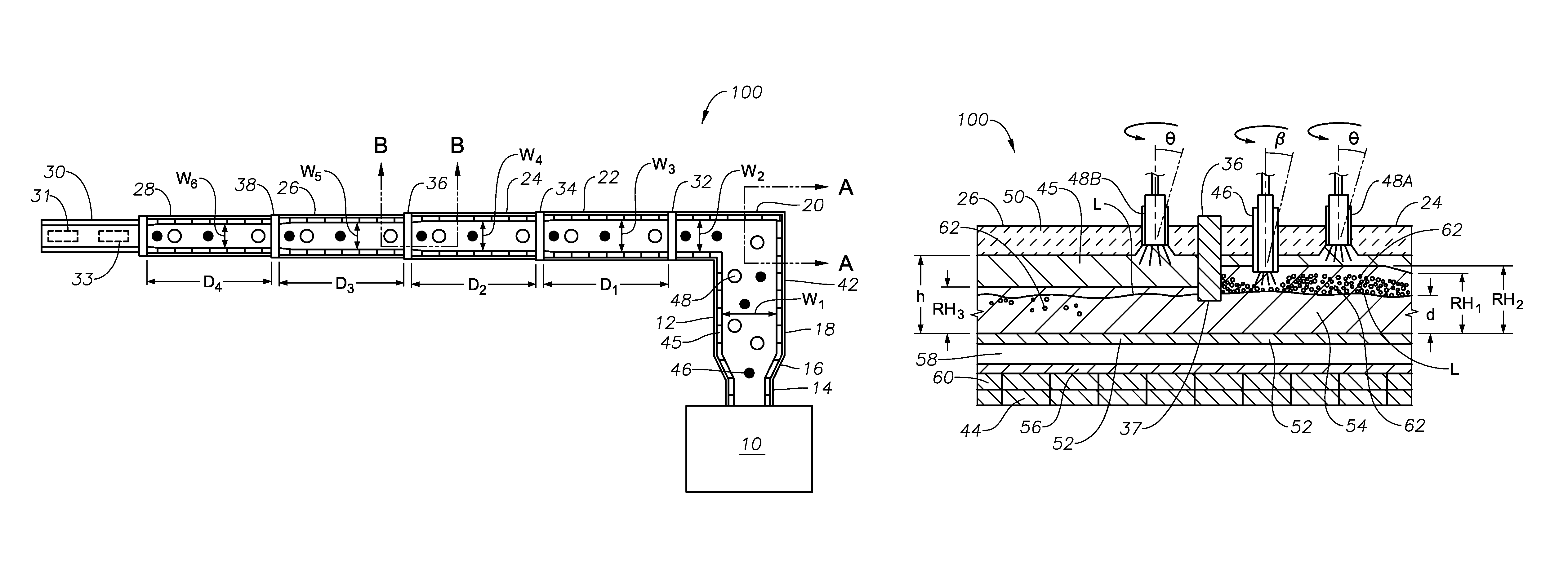
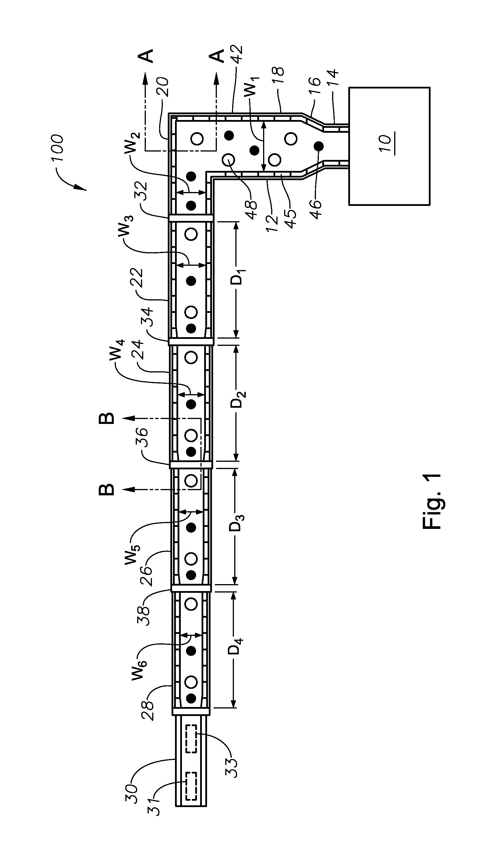
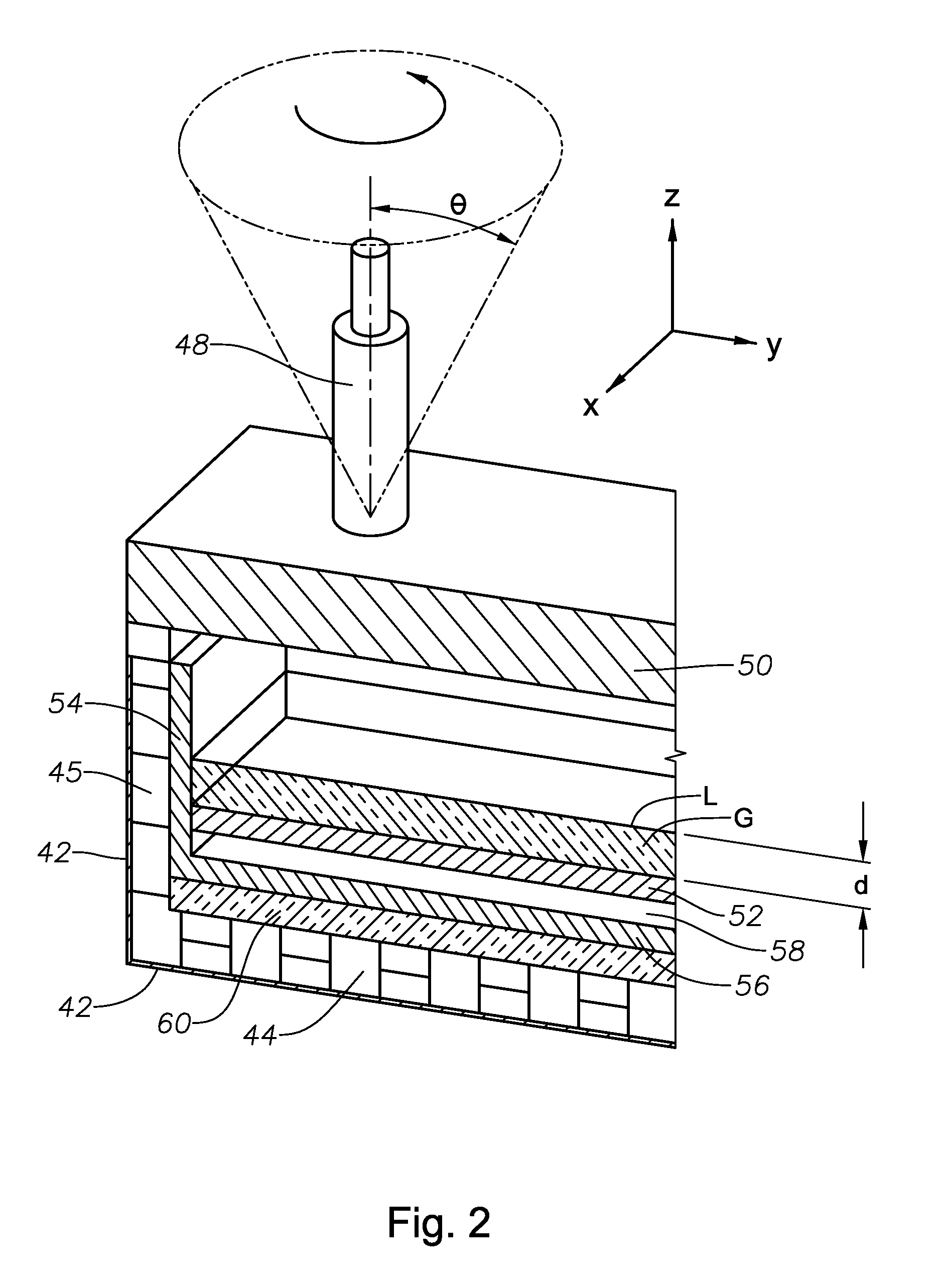
[0044]As explained briefly in the Background, one drawback to submerged combustion is the tendency of the molten glass to foam, either from glass-forming reactions, combustion products, or both...


PUM

PropertyMeasurementUnit
depthaaaaaaaaaa
depthaaaaaaaaaa
depthaaaaaaaaaa

Abstract

Channel apparatus for use with submerged combustion systems and methods of use to produce glass. One channel apparatus includes a flow channel defined by a floor, a roof, and a wall structure connecting the floor and roof, the flow channel divided into sections by a series of skimmers. Channel apparatus include both high and low momentum combustion burners, with one or more high momentum combustion burners positioned immediately upstream of each skimmer in either the roof or sidewall structure, or both, and one or more low momentum combustion burners positioned immediately downstream of each skimmer in either the roof, the sidewall structure, or both, and positioned to transfer heat to the molten mass of glass without substantial interference from foamed material. Certain embodiments include increased height of glass-contact refractory, in particular immediately upstream of the skimmers.

Description

CROSS-REFERENCE TO RELATED APPLICATIONS[0001]This application may be related to assignee's U.S. non-provisional patent application Ser. No. 13 / 268,130, filed Oct. 7, 2011, and to assignee's U.S. non-provisional patent application Ser. No. 13 / 458,211, filed April 27, which are both incorporated by reference herein.BACKGROUND INFORMATION[0002]1. Technical Field[0003]The present disclosure relates generally to the field of combustion furnaces and methods of use to produce glass, and more specifically to systems and methods for reducing foam or its impact during manufacture of glass using submerged combustion melters.[0004]2. Background Art[0005]Submerged combustion melting (SCM) involves melting glass batch materials to produce molten glass by passing oxygen, oxygen-air mixtures or air along with a liquid, gaseous fuel, or particulate fuel in the glass batch, directly into a molten pool of glass usually through burners submerged in a glass melt pool. The introduction of high flow rates...

Claims


Application Information

Patent Timeline
Patent Type & Authority Patents(United States)
IPC IPC(8): C03B5/20C03B5/16
CPCC03B7/02C03B7/06C03B5/2356C03B5/205C03B5/202
Inventor HUBER, AARON MORGANMARTIN, MARLON KEITHMOBLEY, JOHN EUFORD
Owner JOHNS MANVILLE CORP
Why Eureka
Try Eureka