
Pneumatically controlled dual mode face seal

a pneumatically controlled, dual-mode technology, applied in the direction of engine seals, mechanical devices, engine components, etc., can solve the problems of high friction torque in the static state, low leakage rate around the seal, and high sealing force, so as to improve the environmental sealing effect, less maintenance, and high friction

Active Publication Date: 2014-04-29
BAE SYST INFORMATION & ELECTRONICS SYST INTERGRATION INC
View PDF6 Cites 0 Cited by
  • Summary
  • Abstract
  • Description
  • Claims
  • Application Information

AI Technical Summary

Benefits of technology

The invention is a pneumatically powered, dual mode, rotational seal that can gas tightly seal two components in a static state and easily rotate them in a dynamic state with low friction. The seal can create a high-quality gas bearing with very low friction to easily rotate the turret. It requires minimal gas usage and has a low leakage rate when in the static mode. This seal is much more durable and requires less maintenance than other rotational seals. This invention solves problems of previous seals by providing a seal with both high sealing force and low friction torque in the static state. It also allows for quick and easy conversion from a dynamic to static state and vice versa.

Problems solved by technology

Thus, there is a high sealing force, a low leak rate around the seal, and a high friction torque in the static state.

Method used


Image

  • Pneumatically controlled dual mode face seal
  • Pneumatically controlled dual mode face seal
  • Pneumatically controlled dual mode face seal

Examples


Embodiment Construction

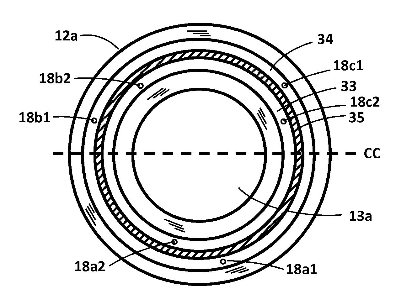
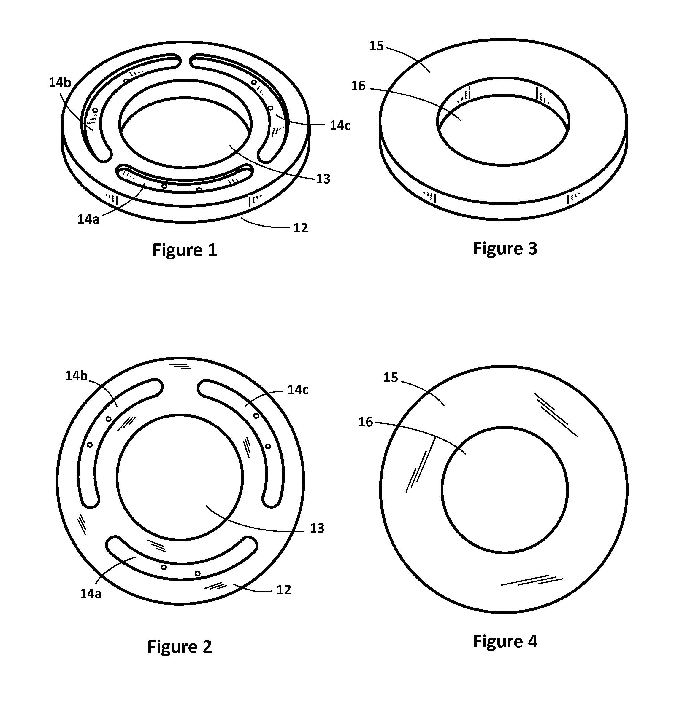
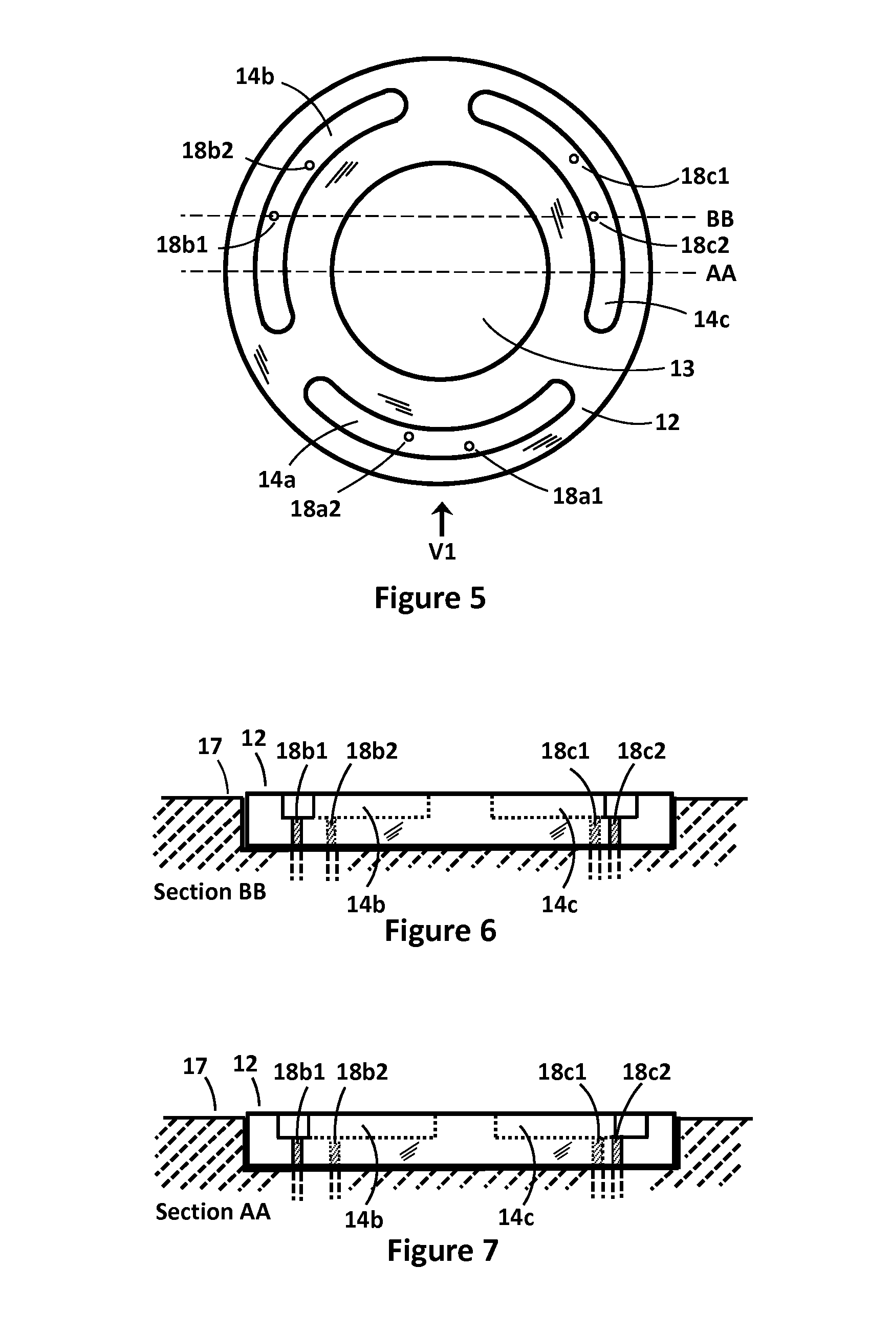
[0028]The invention is a novel pneumatically controlled, dual mode, two part, face seal used between two elements where one of the elements will rotate with respect to the other of the two elements. The novel dual mode face seal provides low friction, low leak rate, and much increased time between maintenance actions. The two modes or states are a first static mode and a second dynamic mode. In the static mode there is an air and liquid tight seal between the two parts of the face seal and in the dynamic mode an air bearing is created between the two parts of the face seal. The air bearing permits the two parts of the face seal to easily rotate with respect to each other.

[0029]More specifically, in the preferred embodiment of the invention described in detail herein, the two elements between which the face seal is mounted are a turret (e.g. a rotatable dome) and a base on which the turret is mounted. The turret is element number 21 in FIG. 11 and the base is element number 17 in FIG...


PUM


Abstract

A pneumatically controlled, two part, rotational face seal is disclosed that has dual modes of operation. There is a first, static mode where a face of each of the two parts of the seal touch each other and provide an air, liquid and water vapor tight, very low leakage rate with high rotational friction between the two parts of the seal. In the second, dynamic mode wherein the two parts of the seal are separated by inert gas and the face seal functions as a gas bearing having very low rotational friction as the two parts are rotated with respect to each other. One part of the seal may be attached to a rotatable turret and the other part may be attached to a base on which the turret is mounted.

Description

CROSS REFERENCE TO RELATED APPLICATIONS[0001]This application claims the benefit of Provisional Patent Application Ser. No. 61 / 510,096 filed Jul. 21, 2011.STATEMENT OF GOVERNMENT INTEREST[0002]The invention was made with United States Government assistance under contract No. W56 HZV-05-C-0724 awarded by the US Army. The United States Government has certain rights in the invention.FIELD OF THE INVENTION[0003]The present invention relates to rotational seals, and more specifically to pneumatically powered rotational seals.BACKGROUND OF THE INVENTION[0004]Transparent spherical domes mounted on a base do not require dynamic seals, but require very precise mechanical centration of interior gimbal mechanisms, are expensive and often fragile, or exhibit high optical scattering. Spring loaded rotary Teflon seals are in common use, but rotational friction is often higher than desired, the seal often has greater leakage than desirable when the gimbal mechanism is not rotating, and seal replac...

Claims


Application Information

Patent Timeline
Patent Type & Authority Patents(United States)
IPC IPC(8): F16J15/34
CPCF16J15/3412F16J15/342F16J15/34
Inventor JOHNSON, PHILIP, M
Owner BAE SYST INFORMATION & ELECTRONICS SYST INTERGRATION INC
Learn More