
Lighting fixture for bicycle

a technology for bicycles and light fixtures, applied in the field of bicycle accessories, can solve the problems of increasing manufacturing costs, reducing the design flexibility of face shapes, and requiring a lot of labor and time for reflector shape-forming molds, so as to save bicycle lighting fixture fabrication time, labor and cost. , the effect of enhancing the face shape design flexibility

Inactive Publication Date: 2014-04-29
YANG SHUN LI
View PDF1 Cites 0 Cited by
  • Summary
  • Abstract
  • Description
  • Claims
  • Application Information

AI Technical Summary

Benefits of technology

[0008]The present invention has been accomplished under the circumstances in view. It is the main object of the present invention to provide a bicycle lighting fixture, which makes the design of the reflector to be more flexible and easy.
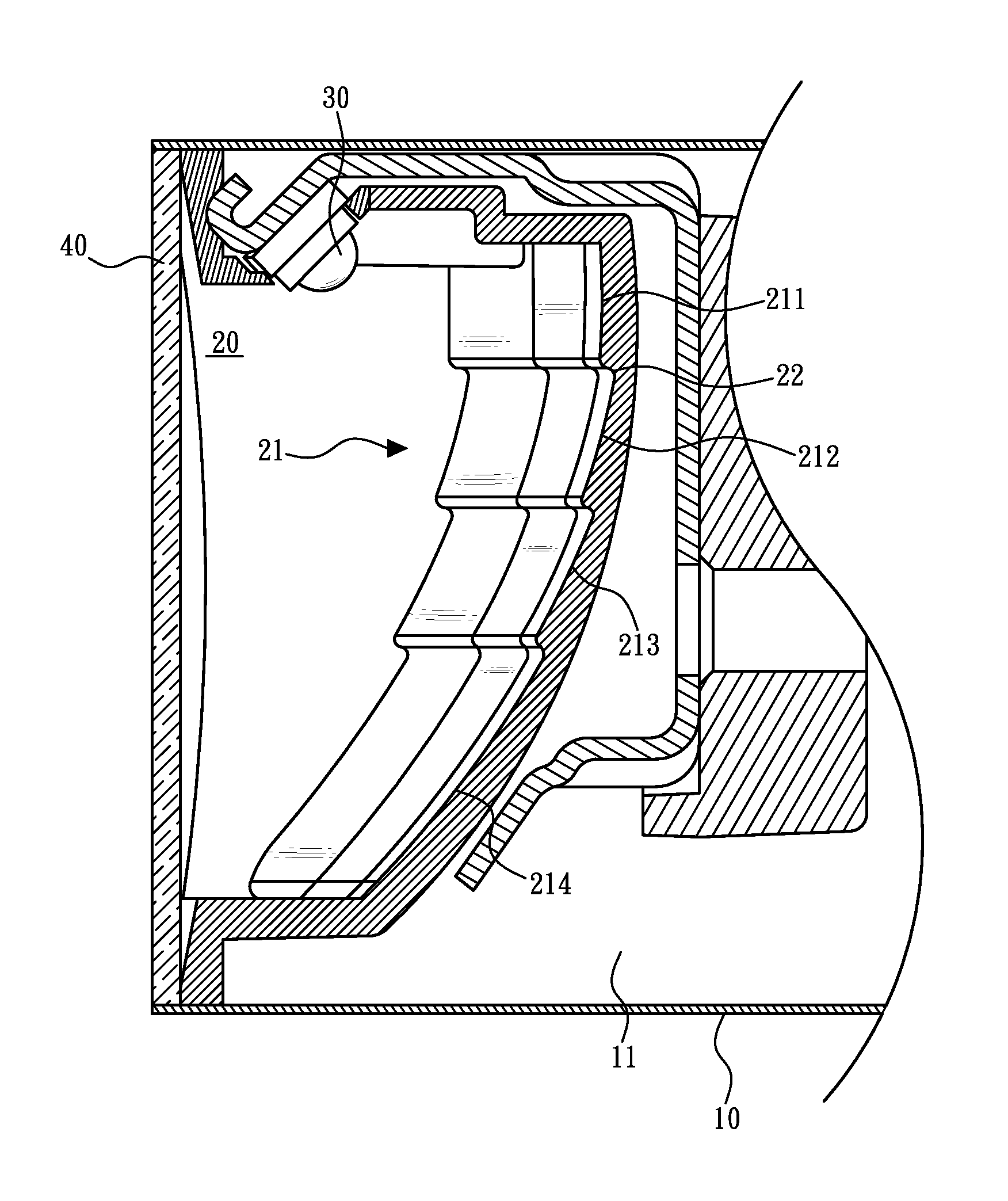
[0010]Because the reflecting surface areas of the curved reflecting surface are of non-continuous multi-step design, the face shape design of the curved reflecting surface is simple, and the reflecting surface areas of the curved reflecting surface can reflect light onto the expected area. Preferably, the reflecting surface area at the top side is configured to reflect light onto a nearby place below the bicycle lighting fixture; the reflecting surface area at the bottom side is configured to reflect light onto a relative far place. Thus, reflecting surface areas at different elevations can satisfy different luminance requirements. Instead of continuous curvature variation, the invention has different reflecting surface areas of the curved reflecting curve be disposed at different elevations and connected together by respective terrace surfaces, facilitating the face shape design of the curved reflecting surface, enhancing face shape design flexibility, and saving much bicycle lighting fixture fabrication time, labor and cost.

Problems solved by technology

This design of the reflecting surfaces of the reflector complicates the design and fabrication of the shape-forming mold for reflector.
In consequence, the fabrication of the reflector requires much labor and time, increasing the manufacturing cost.

Method used


Image

  • Lighting fixture for bicycle
  • Lighting fixture for bicycle
  • Lighting fixture for bicycle

Examples


Embodiment Construction

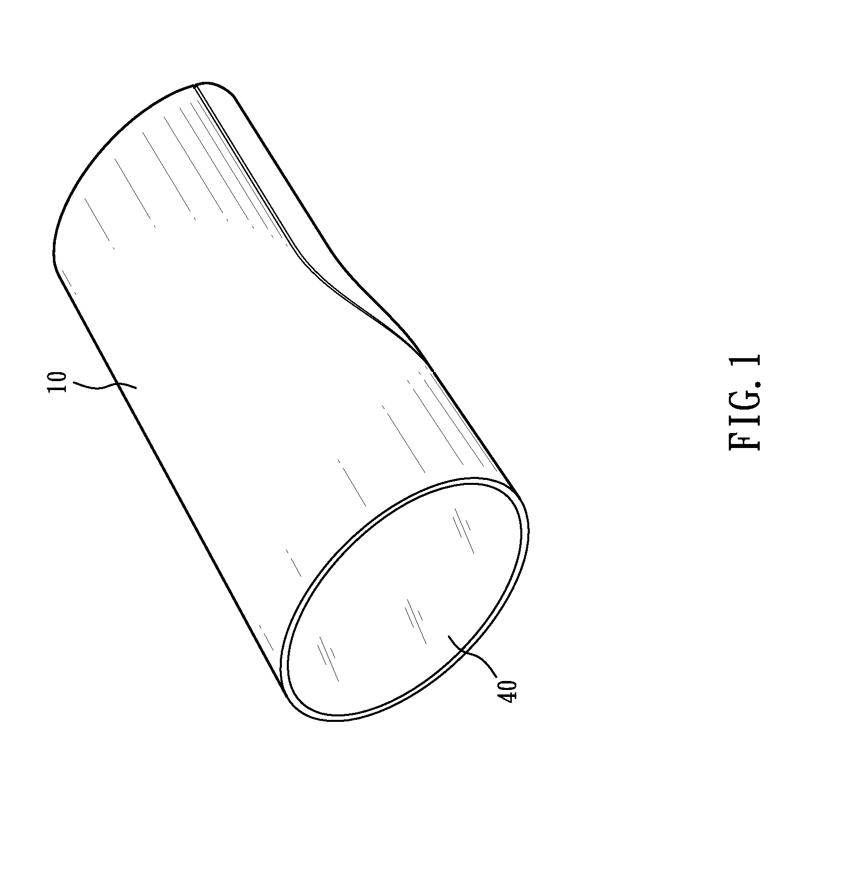
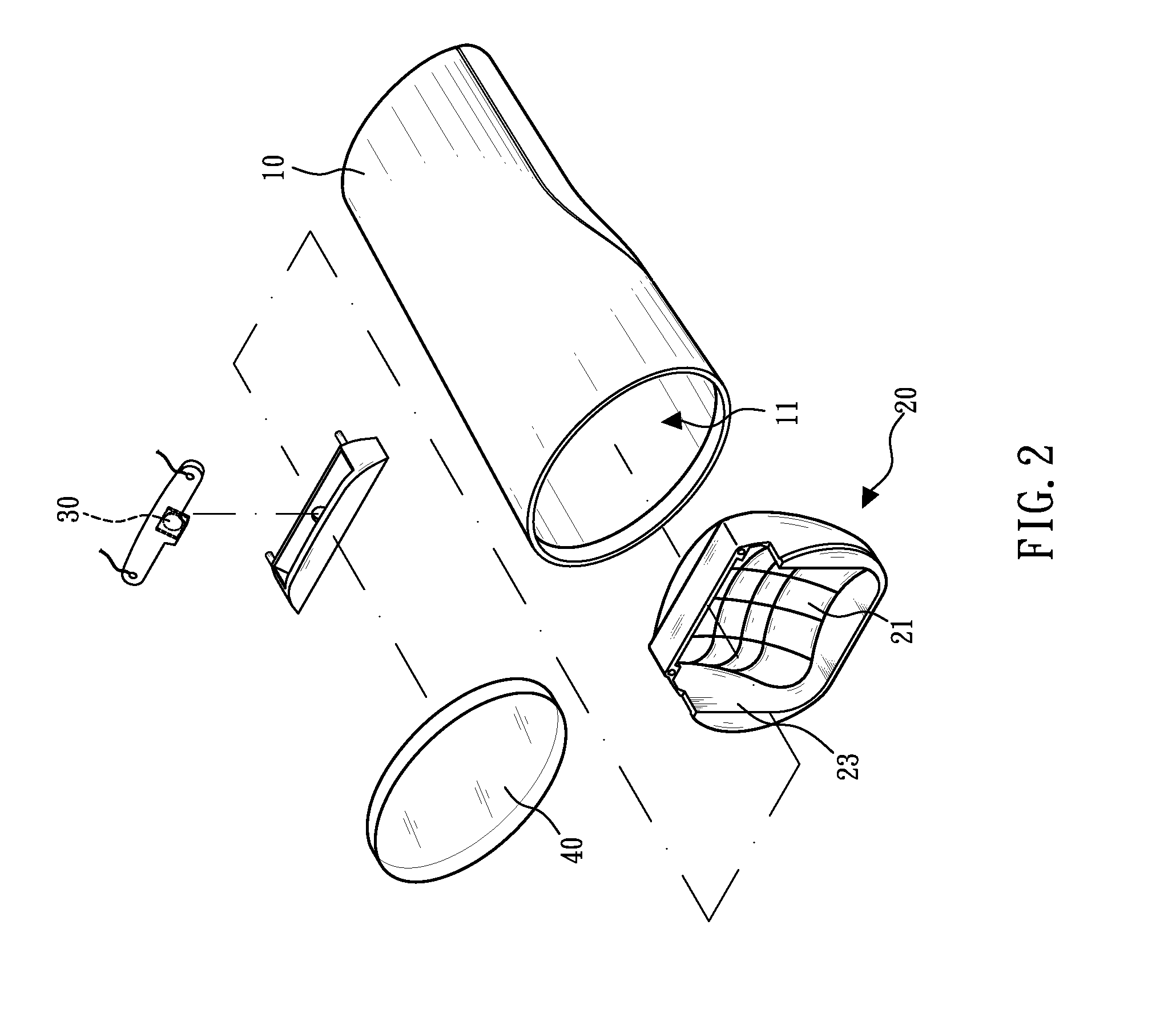
[0017]Referring to FIGS. 1-3, a bicycle lighting fixture in accordance with the present invention is shown. The bicycle lighting fixture comprises a housing 10, a reflector 20, a light source 30, and a lens 40.

[0018]The housing 10 is mountable on a bicycle, defining therein an accommodation chamber 11 adapted for accommodating the reflector 20, the light source 30, the lens 40 and power supply-related devices, such as battery module (not shown) and related electrical wires (not shown).

[0019]The light source 30 is mounted in the accommodation chamber 11 inside the housing 10, and adapted to emit light toward the reflector 20. Preferably, the light source 30 is a high performance light emitting diode that slopes downward at 45° relative to an imaginary horizontal reference line, enabling the emitted light to fully fall upon a predetermined surface of the reflector 20.

[0020]The reflector 20 is preferably configured in a rectangular shape in the front direction. Further, the reflector 2...


PUM


Abstract

A bicycle lighting fixture includes a housing defining therein an accommodation chamber, a reflector mounted in the accommodation chamber and a light source mounted in the accommodation chamber for emitting light onto the reflector. The reflector provides a curved reflecting surface facing toward the outside of the accommodation chamber and defining a plurality of reflecting surface areas at different elevations and a terrace surface connected between each two adjacent reflecting surface areas.

Description

BACKGROUND OF THE INVENTION[0001]1. Field of the Invention[0002]The present invention relates to bicycle accessories and more particularly to a lighting fixture for use in a bicycle.[0003]2. Description of the Related Art[0004]A bicycle lighting fixture enhances bicycle riding safety. More particularly, when riding a bicycle at night, in a tunnel, or under an insufficient lighting environment, the lighting fixture on the bicycle provides lighting for enabling the bicycle rider to see the road condition and alerting vehicles in the opposing direction. In order to achieve the aforesaid targets, some countries and areas define standard regulations on bicycle lighting fixtures. Among them, German defines strict rules on bicycle lighting fixtures so thoroughly as to ensure a high level of safety. The related German standard is called “TA23” and it's found within StVZO (anything related road & traffic). Imagine a wall 10 m away from the light and 90 deg to the beam. The wall is at least 2...

Claims


Application Information

Patent Timeline
Patent Type & Authority Patents(United States)
IPC IPC(8): F21V7/00
CPCB62J6/00B62J6/02B62J6/20
Inventor TSAO, JUNG-CHOU
Owner YANG SHUN LI
Learn More