Drive control circuit, emission control circuit, communication apparatus and drive control method

a technology of emission control circuit and drive control circuit, which is applied in the direction of pulse generator, pulse technique, instruments, etc., can solve the problems of preventing any attempt at miniaturization of such a system

Active Publication Date: 2005-09-15
ROHM CO LTD
View PDF4 Cites 17 Cited by
  • Summary
  • Abstract
  • Description
  • Claims
  • Application Information

AI Technical Summary

Benefits of technology

[0008] The present invention has been made in view of the foregoing circumstances and to solve the aforementioned problems, and an object thereof is to provide a drive control method capable of controlling a load with relative ease and flexibility and to provide a compact drive control circuit, an emission control circuit and a communication apparatus to realize said method.
[0009] A preferred embodiment according to the present invention relates to a drive control circuit comprises: an initial-value setting circuit which sets an initial value of pulse width when a load is driven using pulse-width modulation; a time setting circuit which sets a period of an equal pulse width; and a slope control circuit which varies the pulse width gradually in units of minimum modulation every time the period elapses from the beginning of driving the load. The period may be set by a multiple of cycle of the pulse width modulation. According to this mode of carrying out the invention, the initial value of pulse width and the period of an equal pulse width are set, so that the pulse width can be varied gradually by varying the pulse width in units of minimum modulation every time the period elapses from the beginning of driving the load. As a result, a drive control circuit which is simply and conveniently structured and is also highly flexible can be provided.
[0011] Another preferred embodiment according to the present invention relates to an emission control circuit. This emission control circuit comprises: a plurality of light emitting elements; a drive circuit which drives respectively the light emitting elements by pulse width modulation; an initial-value setting circuit which sets initial values of pulse width in the pulse width modulation to the light emitting elements, respectively; a time setting circuit which sets a period of an equal pulse width to the respective light emitting elements; and a slope control circuit which varies the pulse width gradually in units of minimum modulation for each of the light emitting elements every time a period which is set for each of the light emitting elements elapses from the beginning of driving the each of the light emitting elements. According to this mode of carrying out the invention, the initial value of pulse width and the period of an equal pulse width are set for each of the plurality of light emitting elements, so that the pulse width can be varied gradually by varying the pulse width in units of minimum modulation every time the period elapses from the beginning of driving the load. As a result, a drive control circuit with relative ease and flexibility can be provided.

Problems solved by technology

According to this structure, a desired duty ratio may be obtained, but an oscillation circuit is always required to generate a pulse signal, which is a hindrance to any attempts at miniaturization of such a system.

Method used


Image

  • Drive control circuit, emission control circuit, communication apparatus and drive control method
  • Drive control circuit, emission control circuit, communication apparatus and drive control method
  • Drive control circuit, emission control circuit, communication apparatus and drive control method

Examples


first embodiment

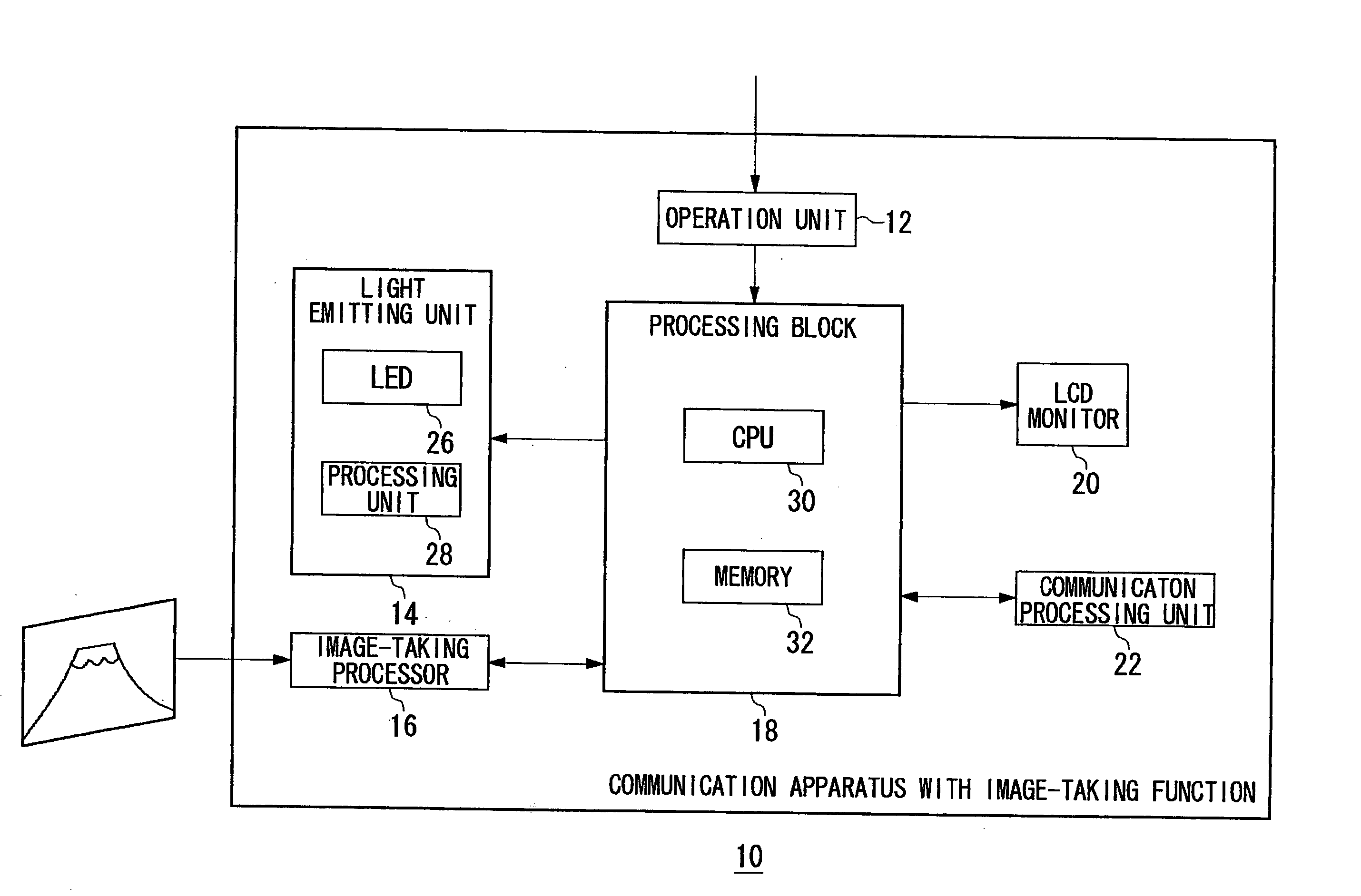
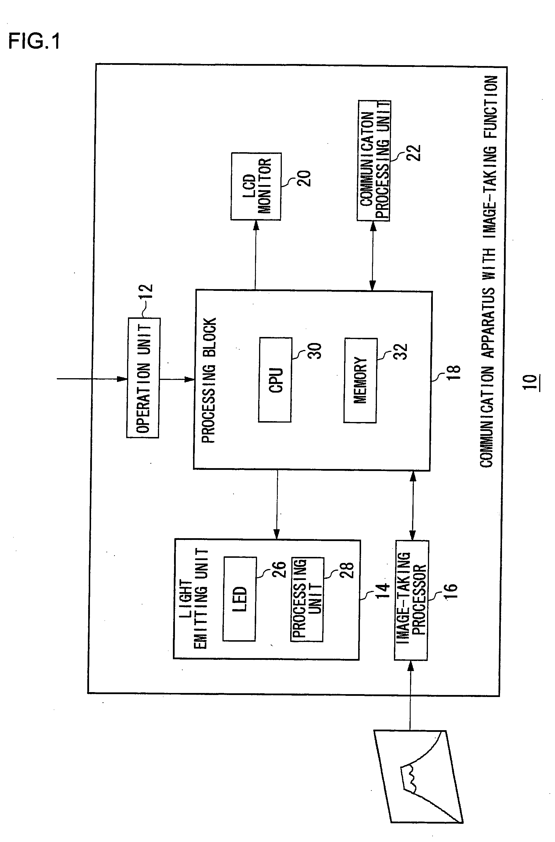
[0035]FIG. 1 illustrates a structure of a communication apparatus with an image-taking function 10 according to a first embodiment of the present invention. The communication apparatus with an image-taking function 10 includes an operation unit 12, a light emitting unit 14, an image-taking processor 16, a processing block 18, an LCD monitor 20 and a communication processing unit 22. The light emitting unit 14 includes LEDs 26 and a processing unit 28, and the processing block 18 includes a CPU 30 and a memory 32. In the present embodiment, the above-described emission control circuit corresponds to a light emitting unit 14 shown in FIG. 1.

[0036] The communication processing unit 22 performs a processing necessary for communication. Here a PDC (Personal Digital Cellular) system is assumed as a mobile telephone system, but it may be such other system as a personal handyphone system (PHS) or a CDMA (Code Division Multiple Access) type mobile communication system.

[0037] The image-taki...

second embodiment

[0111] In the first embodiment, the first PWM circuit 134a, the second PWM circuit 134b and the third PWM circuit 134c control individually the respective above-described emission control processings relating to the first LED 26a, the second LED 26b and the third LED 26c. In a second embodiment, in contrast thereto, emission control periods for a plurality of LEDs are mutually synchronized and whether or not to carry out an emission control processing for each LED is determined and controlled accordingly, so that the color tone of an emitted color realized by a plurality of LEDs is controlled.

[0112]FIG. 12 illustrates a structure of a drive control circuit 136 according to a second embodiment of the present invention. Here, component parts other than a communication apparatus with an image-taking function 10 and the drive control circuit in the light emitting unit 14 are similar to those described in the first embodiment. The drive control circuit 136 according to the second embodi...


PUM


Abstract

A drive control circuit sends out pulse signals of various pulse signals so as to control the light emission amount and luminance of LEDs by gradually increasing and decreasing the pulse width in predetermined cycles during predetermined periods based on parameters supplied from an LED drive controller that determine a first emission control processing period, a second emission control processing period, first to fourth slope periods and the like. The tone of an emitted color realized by a plurality of LEDs is controlled by synchronizing the periods of time of light emission control processings.

Description

BACKGROUND OF THE INVENTION [0001] 1. Field of the Invention [0002] The present invention relates to a drive control circuit, an emission control circuit utilizing the drive control circuit, a communication apparatus provided with the emission control circuit and a drive control method, and it particularly relates to a technology by which to drive and control a load using the pulse-width modulation. [0003] 2. Description of the Related Art [0004] Battery-driven type mobile devices, such as cellular phones or PDAs (Personal Digital Assistants) use LED (Light-Emitting Diode) devices for various purposes, such as a backlight of an LCD (Liquid Crystal Display), a flash for an attached CCD (Charge-coupled device) camera or blinking of LED elements with different emission colors. Reference (1) in the following Related Art List, for instance, discloses a system in which various colors are emitted by mixing blue, green and red emitted by their respective LED elements. Since the emission of ...

Claims


Application Information

Patent Timeline
Patent Type & Authority Applications(United States)
IPC IPC(8): H01L31/036H01L33/00H03K3/00H04B1/38H04M1/00
CPCH04M1/22H05B33/0818Y02B20/346H05B33/0866H05B33/0857H05B45/24H05B45/20H05B45/38H05B47/155H03K7/08G09G3/32H04M1/02Y02B20/30
Inventor YAMAMOTO, ISAOITO, TOMOYUKIIWAKI, HIROYUKI
Owner ROHM CO LTD
Why Eureka
Try Eureka