Loading method of FPGA and device thereof

A loading device and configuration file technology, applied in the electronic field, can solve the problems of slow speed, inconvenient circuit function modification, high cost of configuring chips, etc., and achieve the effect of easy modification

Active Publication Date: 2012-09-12
INST OF MICROELECTRONICS CHINESE ACAD OF SCI
View PDF6 Cites 15 Cited by
  • Summary
  • Abstract
  • Description
  • Claims
  • Application Information

AI Technical Summary

Problems solved by technology

[0004] At present, FPGA manufacturers generally provide proprietary configuration chips to complete chip loading, but the cost of configuration chips is high, and only one configuration file is saved, so that the FPGA chip can only have one circuit function. modification, the configuration tool provided by the merchant is required to erase the configuration chip and then write a new configuration file
[0005] This proprietary way of configuring the chip is expensive, and it is inconvenient and slow to modify the circuit function.

Method used


Image

  • Loading method of FPGA and device thereof
  • Loading method of FPGA and device thereof
  • Loading method of FPGA and device thereof

Examples


Embodiment Construction

[0030] In order to make the above objects, features and advantages of the present invention more comprehensible, specific implementations of the present invention will be described in detail below in conjunction with the accompanying drawings.

[0031] In the following description, a lot of specific details are set forth in order to fully understand the present invention, but the present invention can also be implemented in other ways different from those described here, and those skilled in the art can do it without departing from the meaning of the present invention. By analogy, the present invention is therefore not limited to the specific examples disclosed below.

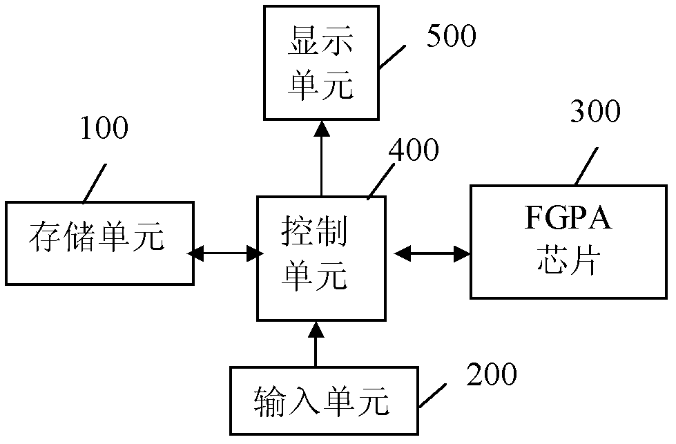
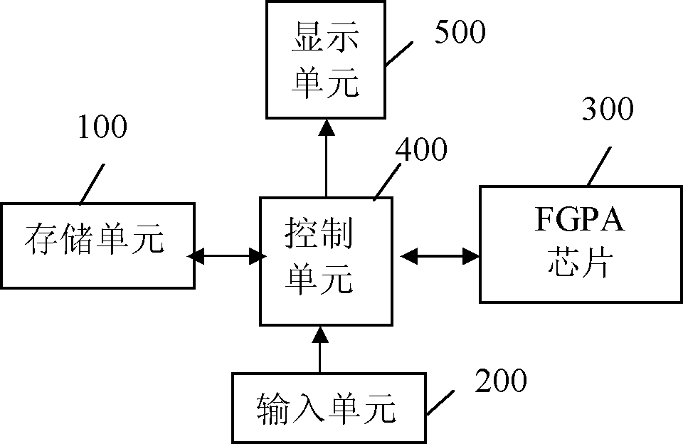
[0032] see figure 1 as shown, figure 1 It is a structural schematic diagram of the FPGA loading device of the embodiment of the present invention. The loading device of FPGA of the present invention comprises: storage unit 100, input unit 200, FPGA chip 300 and control unit 400;

[0033] Wherein, the storage...


PUM


Abstract

The embodiments in the invention disclose a loading device of an FPGA, comprising: a memory unit, an input unit, FPGA chips and a control unit; wherein the memory unit is connected to the control unit and is used for storing at least a configuration file; the input unit is connected to the control unit and is used for inputting identification information of the required configuration file to the control unit; the control unit is connected mutually with FPGA chips and is used for selecting corresponding configuration file from the memory unit based on inputting identification information of the configuration file and transmitting the selected configuration file to the FPGA chips. Dynamic loading of the FPGA is achieved by the configuration file in the memory unit and convenient for modification of FPGA function and update of the configuration file. The FPGA chips are more flexible and convenient than traditional special-purpose chips.

Description

technical field [0001] The present invention relates to the field of electronic technology, and more specifically, relates to an FPGA loading method and device thereof. Background technique [0002] FPGA (Field-Programmable Gate Array Field Programmable Gate Array) is a semi-custom circuit of ASIC, which has low development cost and short cycle, and in a large FPGA chip, the number of gates is large, and it can realize complex functions. . [0003] The logic running inside the FPGA is saved on a certain storage medium in the form of a configuration file, which needs to be loaded when the power is turned on, and the configuration file is loaded into the FPGA. After the configuration is completed, the FPGA has a certain circuit function and can enter work. state, and after power off, the FPGA returns to a white chip, and the internal logic relationship disappears. If you want to enter the working state again, you need to reload the configuration file. If you want to modify th...

Claims


Application Information

Patent Timeline
Patent Type & Authority Applications(China)
IPC IPC(8): G06F9/445
Inventor 张义恒陈岚雷韶华
Owner INST OF MICROELECTRONICS CHINESE ACAD OF SCI
Why Eureka
Try Eureka