Bearing arrangement

a technology of bearing bush and bearing plate, which is applied in the direction of sliding contact bearings, machines/engines, liquid fuel engines, etc., can solve the problems of ceramic bearing bush damage on heating, and achieve the effects of reducing the expansion of heating, reducing the thermal coefficient, and reducing the occurring forces and stresses in the components

Active Publication Date: 2014-04-29
GRUNDFOS MANAGEMENT AS
View PDF21 Cites 3 Cited by
  • Summary
  • Abstract
  • Description
  • Claims
  • Application Information

AI Technical Summary

Benefits of technology

[0005]With regard to this problem, it is an object of the invention to provide an improved bearing arrangement of a shaft, in particular of a rotor shaft, with which the stresses occurring in a bearing bush or bearing sleeve are reduced.

Problems solved by technology

The problem is the fact that the coefficients of thermal expansion of the shaft, which is manufactured of steel, and of the ceramic bearing bush are very different, which leads to undesirable tensile stresses in the ceramic and thus finally to damage of the ceramic bearing bush on heating.

Method used


Image

  • Bearing arrangement
  • Bearing arrangement
  • Bearing arrangement

Examples


Embodiment Construction

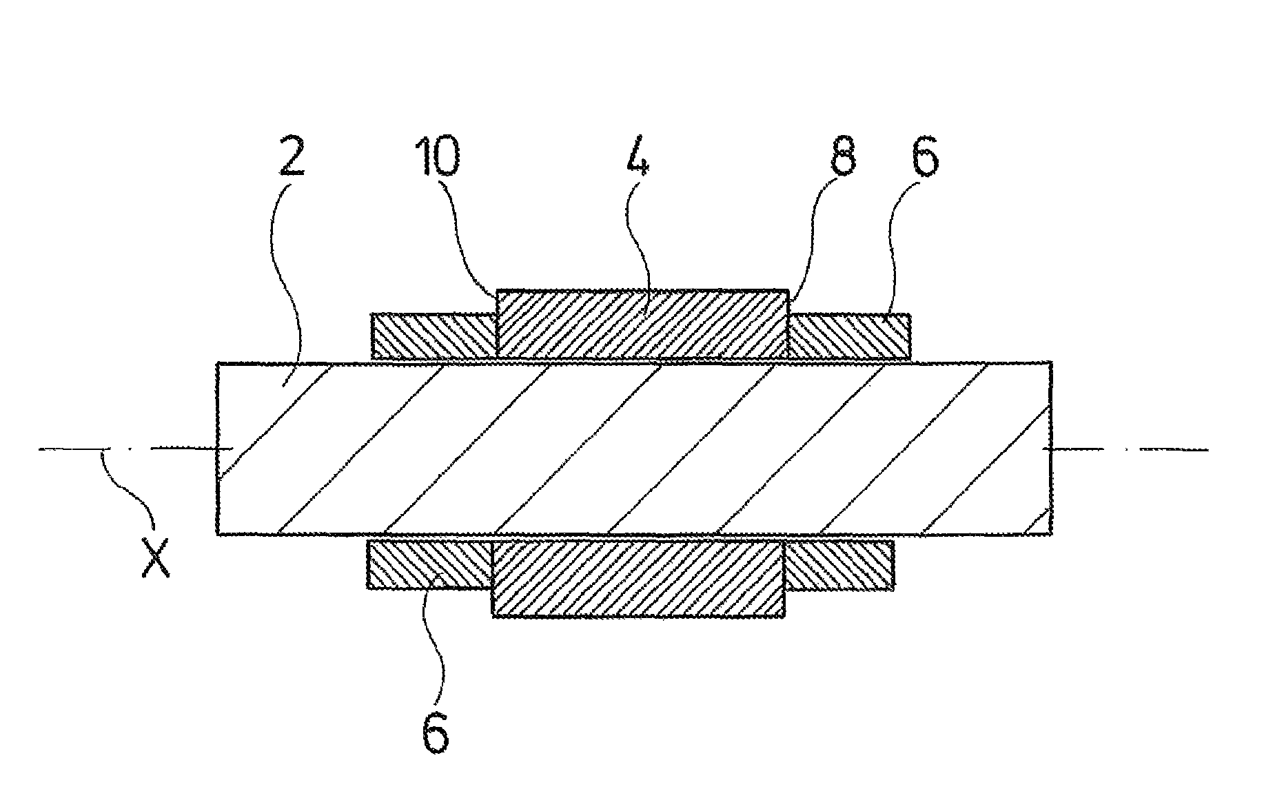
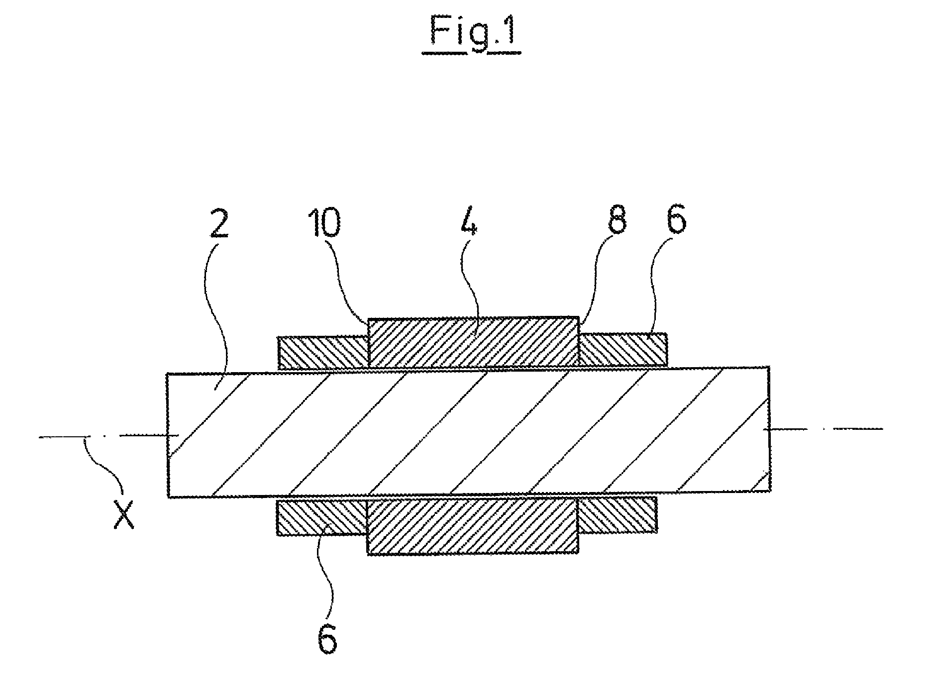
[0032]FIG. 1 schematically shows a bearing arrangement of a shaft, as is known from the state of the art and from which the present invention proceeds. With this bearing arrangement, a ceramic bearing sleeve 4 is arranged on the shaft 2. The bearing sleeve 4 surrounds the shaft 2 in an annular manner and is aligned or centered concentrically to its longitudinal axis X. For this, the bearing sleeve 4 is engaged with the shaft 2 with a positive fit via a profiling which is not shown in detail here. The bearing sleeve 4 in the axial direction is fixed on the shaft 2 via two retaining sleeves 6 which are supported on the shaft 2 in the axial direction, for example on securing rings (not shown). Thereby, at least one of the retaining sleeves 6 may be supported in the axial direction on the shaft 2 via a spring element, in order to be able to compensate with temperature changes length changes of the retaining sleeves 6 and, as the case may be, of the bearing sleeve 4, which result therefr...


PUM


Abstract

A bearing arrangement of a shaft (2) is provided with which an annular bearing sleeve (4) is applied onto the shaft (2). At least in the axial region in which the bearing sleeve (4) is arranged, the shaft (2) includes a profiling extending parallel to its longitudinal axis (X). A corresponding engagement element (12) on the inner periphery of the bearing element (4) engages the profiling with a positive fit. At least one engagement element (12) extends in the direction of the longitudinal axis (X) of the shaft (2) only over a part of the length of the bearing sleeve (4).

Description

CROSS-REFERENCE TO RELATED APPLICATIONS[0001]This application is a Section 371 of International Application No. PCT / EP2008 / 011114, filed Dec. 24, 2008, which was published in the German language on Jul. 16, 2009, under International Publication No. WO 2009 / 086917 A and the disclosure of which is incorporated herein by reference.BACKGROUND OF THE INVENTION[0002]A sliding bearing for a machine shaft, in this example the rotor shaft of a pump assembly, is known for example from European Patent 0 771 957 B1. With this sliding bearing, a bearing bush is applied onto the actual shaft.[0003]With such bearing arrangements, the bearing bush is manufactured of a suitable bearing material, for example bronze or ceramic, while the rotor shaft is usually a conventional steel component. In order to permit a torque transmission from the rotor shaft onto the bearing bush, and to center the bearing bush, it is known to profile the shaft and to design corresponding profiles in the bearing bush, which...

Claims


Application Information

Patent Timeline
Patent Type & Authority Patents(United States)
IPC IPC(8): F16C25/04F16C17/00
CPCF16C17/22F04D29/0465F04D29/628F16C33/043F04D29/047
Inventor VEDSTED, PER FROSTPOULSEN, BRIAN LUNDSTEDGRANN, HELGE
Owner GRUNDFOS MANAGEMENT AS
Why Eureka
Try Eureka