A bearing arrangement for a drive shaft of a turbo-machine, and a turbo-machine including such a bearing arrangement

a technology of bearing arrangement and turbo-machine, which is applied in the direction of sliding contact bearings, machines/engines, liquid fuel engines, etc., can solve the problems of difficult machine, high cost of hard materials, and high cost of manufacturing such a turbo-machine, and achieve the effect of improving the bearing arrangemen

Active Publication Date: 2020-01-09
ROBERT BOSCH GMBH +1
View PDF1 Cites 4 Cited by
  • Summary
  • Abstract
  • Description
  • Claims
  • Application Information

AI Technical Summary

Benefits of technology

[0014]It is an object of the present invention to provide an improved bearing arrangement, for a drive shaft of a turbo-machine, which can overcome at least partially the drawbacks encountered in conventional centrifugal turbo-compressor.

Problems solved by technology

The manufacturing of such a turbo-compressor is expensive and time consuming due particularly to the hard material, such as tungsten carbide, used to make the drive shaft, the first and second axial bearing plates and the bearing sleeve.
Indeed, such a hard material is expensive, and difficult to machine due to its high surface hardness.
Consequently, the provision of gas bearing arrangements further increases the manufacturing cost of a turbo-compressor.

Method used


Image

  • A bearing arrangement for a drive shaft of a turbo-machine, and a turbo-machine including such a bearing arrangement
  • A bearing arrangement for a drive shaft of a turbo-machine, and a turbo-machine including such a bearing arrangement
  • A bearing arrangement for a drive shaft of a turbo-machine, and a turbo-machine including such a bearing arrangement

Examples


first embodiment

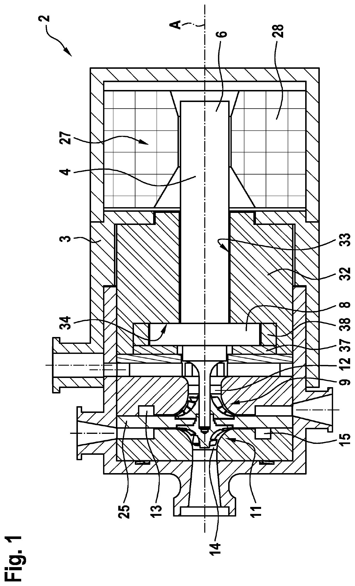
[0066]FIGS. 1 to 3 represent a turbo-machine 2, and particularly a double-stage centrifugal turbo-compressor, according to the invention.

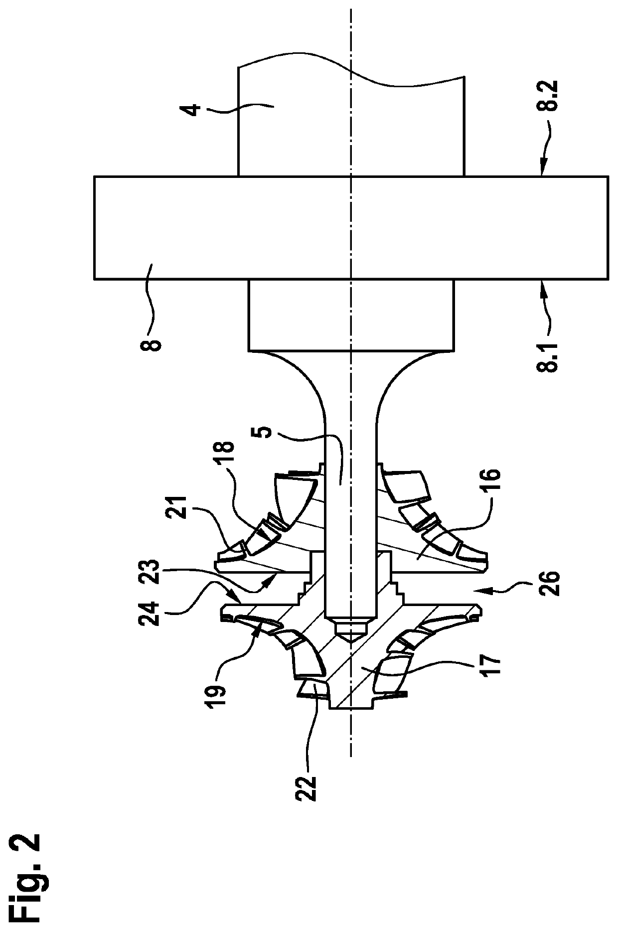
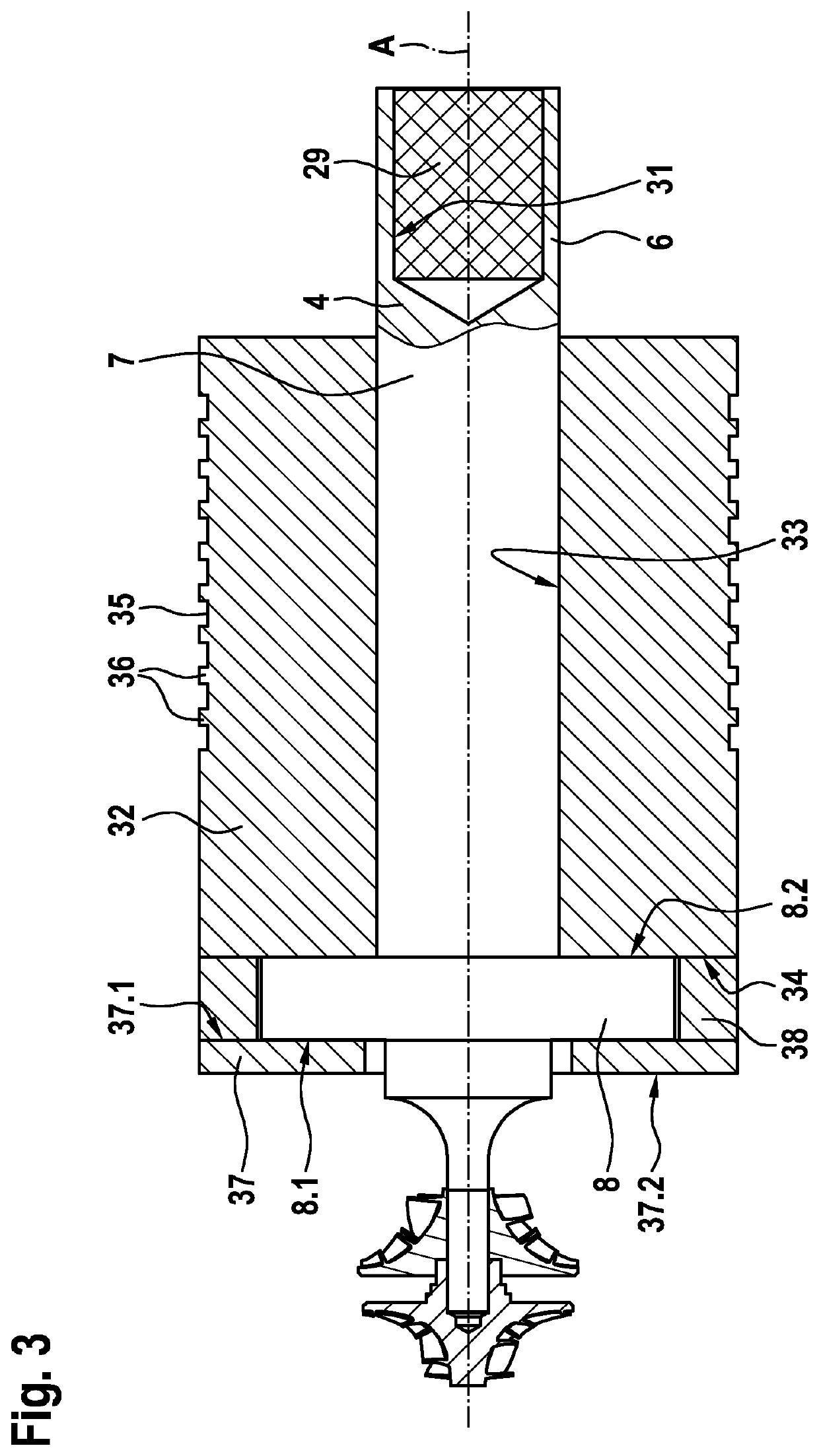
[0067]The turbo-machine 2 includes a casing 3 and a drive shaft 4 rotatably arranged within the casing 3 and extending along a longitudinal axis A. The drive shaft 4 includes an impeller portion 5, a driving portion 6 opposite to the impeller portion 5, and a bearing portion 7 arranged between the impeller portion 5 and the driving portion 6.

[0068]The drive shaft 4 further includes a radial thrust bearing member 8, also named radial flange portion, having a flat disc shape and which extends radially outwardly with respect to the bearing portion 7. The radial thrust bearing member 8 has an outer diameter larger than the outer diameter of the bearing portion 7, and includes a first axial face 8.1 and a second axial face 8.2 opposite to the first axial face 8.1. The radial thrust bearing member 8 may be integrally formed with the bearing portion 7, or...

third embodiment

[0085]FIG. 4 represents a turbo-machine 2 according to the invention which differs from the embodiment shown on FIG. 3 particularly in that it further includes an additional axial bearing plate 39 having an annular disc shape, and in that the additional axial bearing plate 39 includes the axial bearing surface 34 and has an abutment surface 41 opposite to the axial bearing surface 34 and abutting against the gas bearing sleeve 32.1. Advantageously, the additional axial bearing plate 39 is made in molybdenum or in a molybdenum alloy.

[0086]According to the third embodiment, the spacer ring 38 is clamped between the first surface 37.1 of the axial bearing plate 37 and the axial bearing surface 34 of the additional axial bearing plate 39, at radial outer portions of the axial bearing plate 37 and the additional axial bearing plate 39.

[0087]FIG. 5 represents a turbo-machine 2 according to a fourth embodiment of the invention which differs from the third embodiment shown on FIG. 4 particu...


PUM

PropertyMeasurementUnit
Vickers hardnessaaaaaaaaaa
axial distanceaaaaaaaaaa
shapeaaaaaaaaaa

Abstract

The bearing arrangement includes a one-piece gas bearing sleeve (32) configured to rotatably support the drive shaft (4) and made in molybdenum or in a molybdenum alloy, the one-piece gas bearing sleeve (32) including a radial bearing surface (33) configured to Surround the drive shaft (4).

Description

FIELD OF THE INVENTION[0001]The present invention relates to a bearing arrangement for a drive shaft of a turbo-machine, and particularly of a centrifugal turbo-compressor.BACKGROUND OF THE INVENTION[0002]As known, a centrifugal turbo-compressor may include:[0003]a casing,[0004]a drive shaft rotatably arranged within the casing and extending along a longitudinal axis, the drive shaft including a radial thrust bearing member,[0005]a first and a second compression stage configured to compress a refrigerant, the first and second compression stages respectively including a first and a second impeller, the first and second impellers being connected to the drive shaft and being arranged in a back-to-back configuration,[0006]an axial bearing arrangement configured to limit an axial movement of the drive shaft during operation, the axial bearing arrangement including:[0007]a first axial bearing plate and a second axial bearing plate being parallel and each having an annular disc shape, the ...

Claims


Application Information

Patent Timeline
Patent Type & Authority Applications(United States)
IPC IPC(8): F04D29/056F01D25/12F16C3/02F16C17/02F16C33/12
CPCF05D2300/131F04D29/056F01D25/125F16C17/02F16C2204/46F16C3/02F16C2360/44F16C33/121F01D25/166F01D25/22F04D17/122F04D29/023F04D29/0513F04D29/057F16C17/04F16C33/1005
Inventor MARTIGNAGO, CLEMENTBONNEFOI, PATRICEVANDESTEENE, STANROSSON, YVES
Owner ROBERT BOSCH GMBH
Why Eureka
Try Eureka