Housing for an electric machine

a technology for electric machines and housings, applied in the direction of electrical apparatus, dynamo-electric machines, supports/enclosements/casings, etc., can solve the problems of comparatively high production costs of housings of this type, and achieve the effects of less noise, less mechanical instability, and improved mechanical stability

Active Publication Date: 2018-09-27
ROBERT BOSCH GMBH
View PDF10 Cites 1 Cited by
  • Summary
  • Abstract
  • Description
  • Claims
  • Application Information

AI Technical Summary

Benefits of technology

[0009]It is furthermore advantageous if the outer housing is made from aluminum or plastic, in particular polyamide or polypropylene because the outer housing including the cooling ribs integrally formed thereon can in this way be particularly cost effectively manufactured by casting or injection molding.
[0010]It is furthermore advantageous if the plastic of the outer housing contains glass fibers and / or a foam structure. The outer housing becomes more mechanically stable and becomes deformed less as a result of the glass fibers provided in the material of the outer housing, so that the inner housing rests on the cooling ribs of the outer housing while maintaining form and position tolerances and seals said ribs to a great extent so that no or only small leaks occur in the meander-shaped cooling channel. A damping effect on the outer housing is achieved by means of a foam structure of the material of the outer housing, so that undesired noises from components adjacent to the outer housing are prevented. In addition, the foam prevents the shrinking and the warpage of the outer housing when said outer housing is cooled down in the injection molding tool. The foam structure of the outer housing is achieved by a foaming agent being added to the plastic to be foamed. After production, the wall of the outer housing has a foamed core with a compact edge layer in cross-section.
[0011]It is advantageous if the inner housing is made from sheet metal, in particular sheet steel, because the inner housing has thus a particularly good heat conductivity in order to effectively be able to remove the heat from the bearing via the cooling channel of the housing. In addition, the inner housing can be cost effectively manufactured in this way, for example by deep-drawing. Furthermore, an inner housing made from sheet metal has a high thermal resistance.

Problems solved by technology

In addition, the production costs for a housing of this type are comparatively high, as the cooling ribs are formed as a separate part and have to be inserted into the intermediate casing space.

Method used


Image

  • Housing for an electric machine
  • Housing for an electric machine
  • Housing for an electric machine

Examples


Embodiment Construction

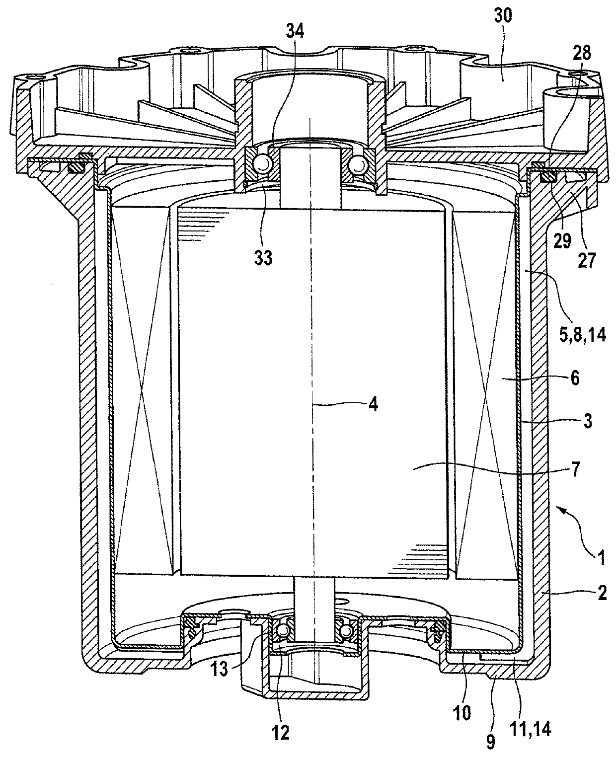
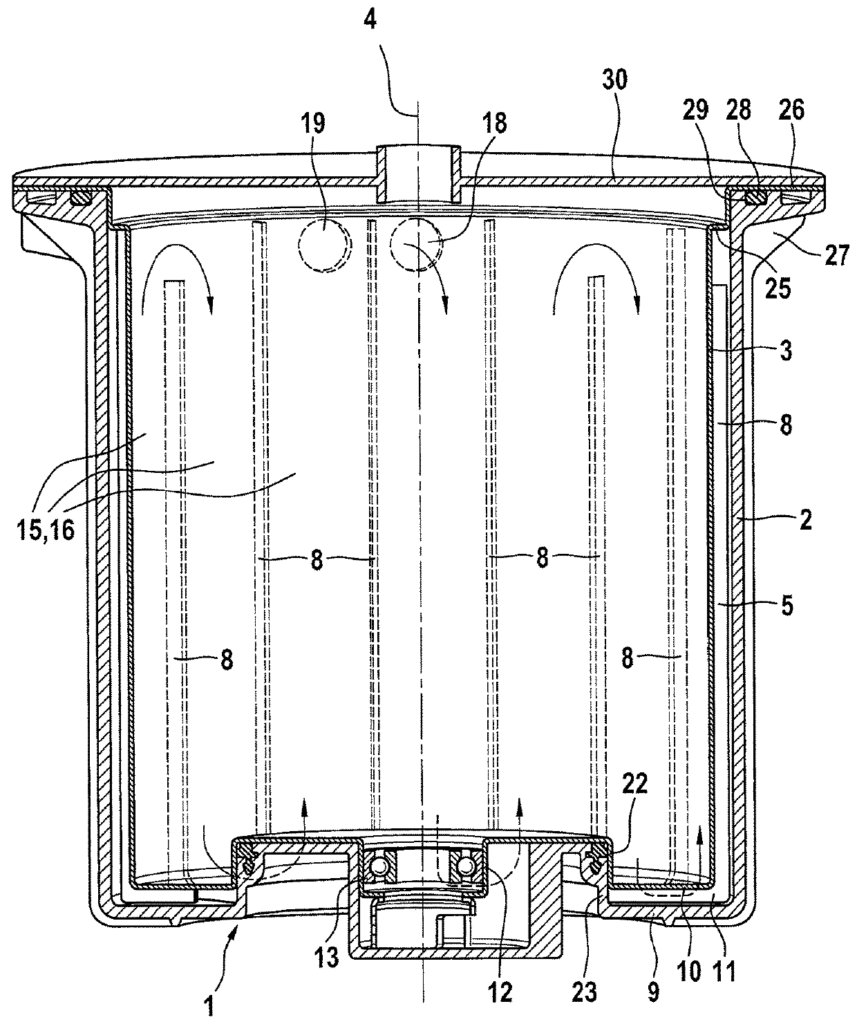
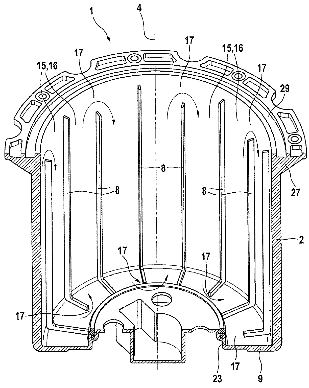
[0017]FIG. 1 shows a sectional view of the housing according to the invention.

[0018]The housing 1 according to the invention is a housing of an electric machine and is used to receive a stator 6 and a rotor 7 of the electric machine and to remove the heat of the electric machine.

[0019]The housing 1 comprises an outer housing 2 and an inner housing 3 arranged in the outer housing 2. An intermediate casing space 5, in which cooling ribs 8 are provided, is formed between the outer housing 2 and the inner housing 3 as seen in a radial direction with respect to a stator axis 4.

[0020]The outer housing 4 and the inner housing 3 are in each case designed pot-shaped and have respectively a base 9, 10. A base intermediate space 11, which is fluidly connected to the intermediate casing space 5, is formed between the base 9 of the outer housing 2 and the base 10 of the inner housing 3. In this way, the intermediate casing space 5 and the base intermediate space 11 form a continuous cooling inte...


PUM


Abstract

Housings are already known having a pot-shaped outer housing, a pot-shaped inner housing arranged in the outer housing and an intermediate casing space, formed between the outer housing and the inner housing in a radial direction with respect to a stator axis, in which cooling ribs, running in the circumferential direction with respect to the stator axis, are provided to form a cooling channel running in a spiral shape. A base intermediate space is formed between the base of the outer housing and the base of the inner housing. A bearing for the rotor shaft is provided in the base of the inner housing and is heated by heat from the electric machine. The spiral-shaped cooling channel for cooling the bearing for the rotor shaft is not guided into the base intermediate space. The cooling of the bearing for the rotor shaft can thus still be improved In addition, the production costs for a housing of this type are comparatively high, as the cooling ribs are formed as a separate part and inserted into the intermediate casing space. In the housing according to the invention, the cooling of the bearing arranged in the base of the inner housing is improved. According to the invention, multiple cooling ribs (8), running in the axial direction, are provided in the intermediate casing space (5), and they extend into the base intermediate space (11) and run in the radial direction in the base intermediate space (11).

Description

BACKGROUND OF THE INVENTION[0001]The invention relates to a housing for an electric machine.[0002]A housing for an electric machine is known from the German patent application DE 10 2005 052 363 A1, having a pot-shaped outer housing, a pot-shaped inner housing arranged in the outer housing and an intermediate casing space formed between the outer housing and the inner housing in a radial direction with respect to the stator axis, in which cooling ribs, running in the circumferential direction with respect to the stator axis, are provided to form a cooling channel running in a spiral shape. A base intermediate space is formed between the base of the outer housing and the base of the inner housing. A bearing for the rotor shaft is provided in the base of the inner housing and is heated by heat from the electric machine. The spiral-shaped cooling channel for cooling the bearing for the rotor shaft is not guided into the base intermediate space. The cooling of the bearing for the rotor ...

Claims


Application Information

Patent Timeline
Patent Type & Authority Applications(United States)
IPC IPC(8): H02K5/18
CPCH02K5/18H02K5/1732H02K5/203
Inventor CARRILLO, CAMILOGOVINDASAMY, KARTHICKSCHOELLIG-ALT, PATRIZIAGEISE, STEPHAN
Owner ROBERT BOSCH GMBH
Why Eureka
Try Eureka