Adjustable camshaft

a camshaft and adjustment technology, applied in the direction of cams, valve arrangements, gearing elements, etc., can solve the problems of increasing the friction occurring in the slide bearing arrangement, and achieve the effect of facilitating emergency running properties

Active Publication Date: 2016-05-19
THYSSENKRUPP PRESTA TECCENTER AG
View PDF5 Cites 2 Cited by
  • Summary
  • Abstract
  • Description
  • Claims
  • Application Information

AI Technical Summary

Benefits of technology

[0004]The object of the invention is to improve the bearing arrangement of cam elements on the outer shaft of an adjustable camshaft. In particular, the object of the present invention is to provide an adjustable camshaft with a simplified construction and simplified installation. Finally, there is the object of minimizing the resulting friction in the bearing arrangement of the cam elements on the outer shaft of the adjustable camshaft.
[0008]A particular advantage arises from the fact that the configuration of the bearing sleeves in the cam elements, in particular with regard to an advantageous material selection, may be adapted to the specific loading of the slide bearing of the cam elements on the outer shaft. According to the embodiment of the invention, the bearing sleeves do not serve simultaneously to mount the camshaft in the cylinder head—which bearing must withstand higher loads—but merely to mount the cam elements on the outer shaft. Due to the smaller action radius of the slide bearing arrangement between the inside of the bearing sleeve and the outside of the outer shaft, the friction of the bearing of the cam elements on the outer shaft is also reduced.
[0009]Particularly advantageously, the bearing sleeve can be pressed into the cam bore. The friction connection thus formed allows the bearing sleeve to be connected rotationally fixedly to the cam element, so as to securely prevent a twist of the bearing sleeve in the cam bore. Also, the bearing sleeve may be pinned in the cam bore to create a form-fit connection between the bearing sleeve and the cam element.
[0015]According to a further advantageous embodiment of the bearing of the cam element on the outer shaft, the bearing sleeve may be made of a bronze material, a brass material or alloys of bronze and brass. Alternatively, the bearing sleeve may comprise a plastic material. The plastic material may for example be a polyoxymethylene (POM) or for example a polyimide (PI). Further advantageously, the inner bearing surface of the bearing sleeve may have a coating which for example comprises a polytetrafluoroethylene coating (PTFE). In particular, the use of PTFE coatings in the bearing sleeve leads to advantageous emergency running properties on deficient lubrication.

Problems solved by technology

Furthermore, the disadvantage results that the bearing sleeves entail an increase in the slide bearing diameter on which the cam elements are mounted rotatably on the outside of the camshaft, unnecessarily increasing the friction occurring in the slide bearing arrangement.

Method used


Image

  • Adjustable camshaft
  • Adjustable camshaft
  • Adjustable camshaft

Examples


Embodiment Construction

[0017]Further measures improving the invention are described below in more detail, together with the description of preferred exemplary embodiments of the invention, with reference to the figures. These show:

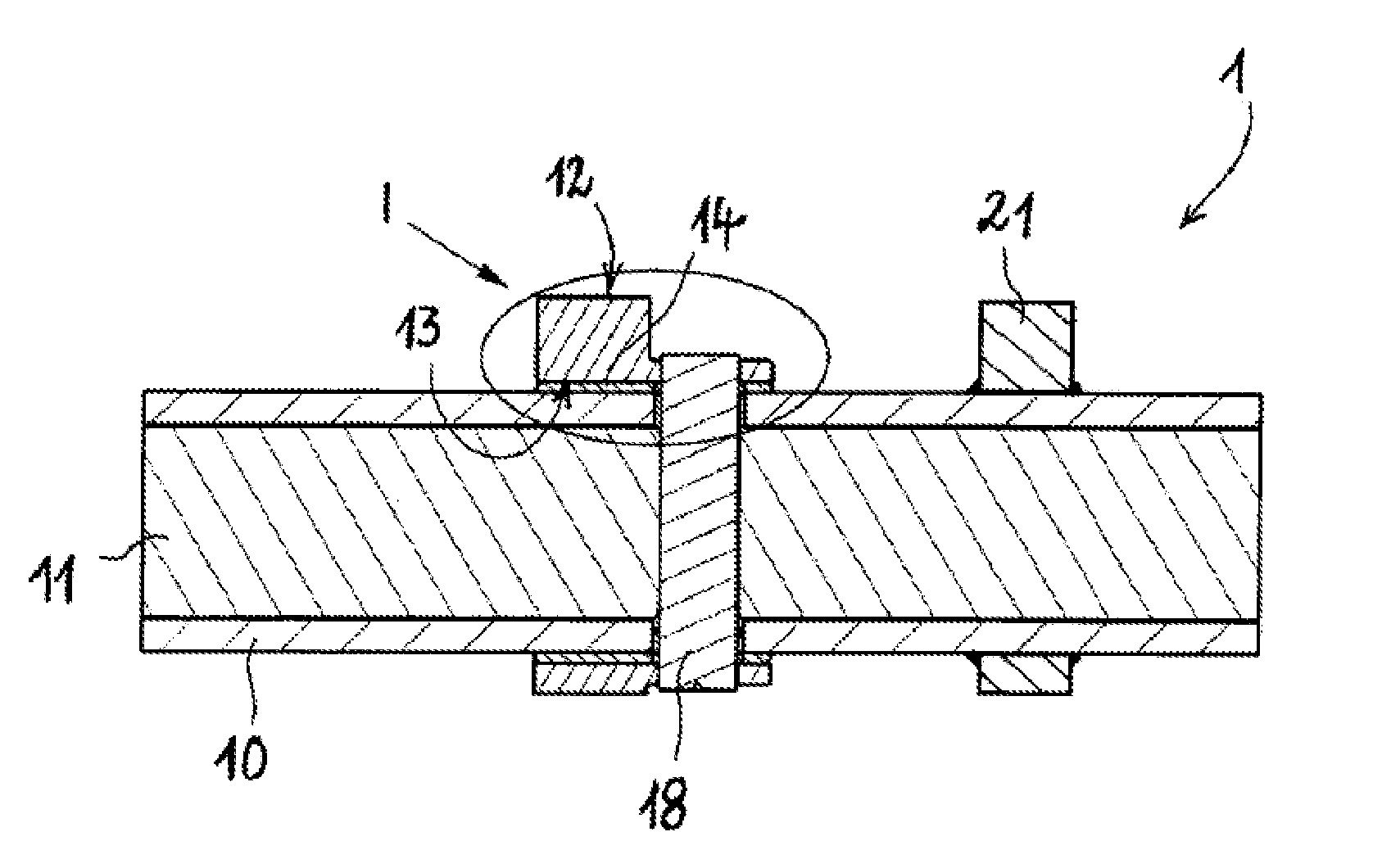
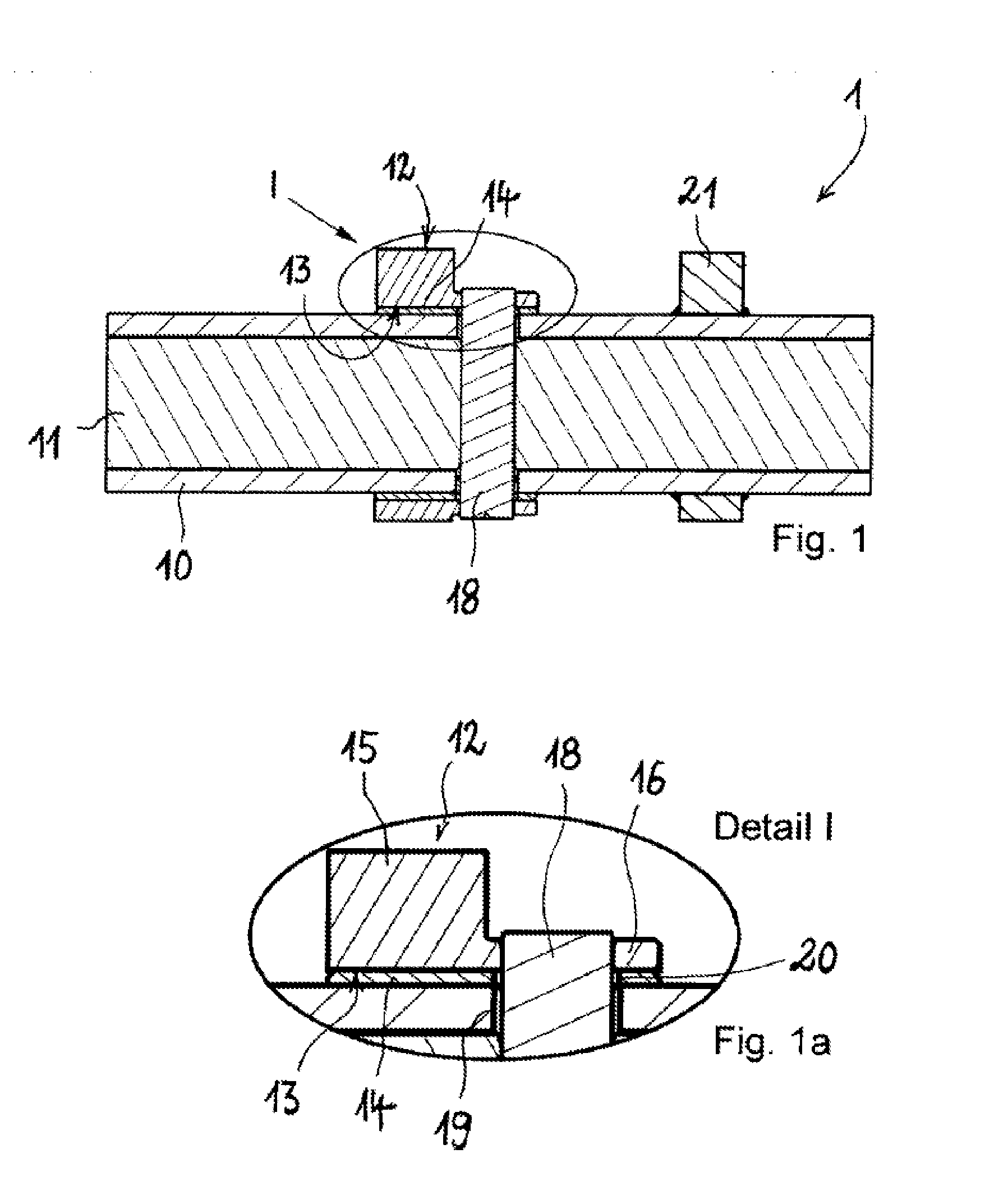
[0018]FIG. 1 a cross-section view of a camshaft according to a first exemplary embodiment of the invention;

[0019]FIG. 1a a detail view I according to FIG. 1;

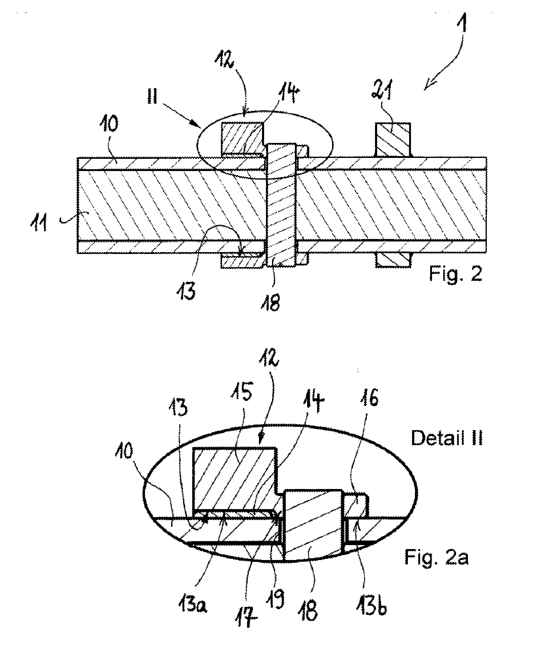
[0020]FIG. 2 an exemplary embodiment of a camshaft in a cross-section view according to a second exemplary embodiment of the invention;

[0021]FIG. 2a a detail view II according to FIG. 2;

[0022]FIG. 3 an exemplary embodiment of a camshaft in a cross-section view according to a third exemplary embodiment of the invention;

[0023]FIG. 3a a detail view III according to FIG. 3.

[0024]FIGS. 1 and 1a show in a cross-section view a first exemplary embodiment of a camshaft 1, wherein FIG. 1a shows the detail I according to FIG. 1. The camshaft 1 is configured as an adjustable camshaft 1 and serves for the valve drive of an internal combu...


PUM


Abstract

An adjustable camshaft can be used in a valve drive of an internal combustion engine. The adjustable camshaft may include an inner shaft rotatably supported by and concentric with an outer shaft. A cam element may be rotatably supported on the outer shaft such that the outer shaft extends through a cam bore of the cam element. The cam element may be rotatably-fixed to the inner shaft, in some cases, by way of a bolt. Further, a bearing sleeve that is rotatably-fixed to the cam element may be inserted within the cam bore such that a slide bearing gap is formed between the bearing sleeve and the outer shaft. Furthermore, in some examples the cam element may be a collared cam that has a cam base body and a cam collar adjacent to one another.

Description

[0001]The present invention concerns an adjustable camshaft for the valve drive of an internal combustion engine, with an outer shaft and an inner shaft running concentrically and held rotatably in the output shaft, wherein at least one cam element with a cam bore is mounted rotatably on the outer shaft, and wherein the cam element is connected rotationally fixedly to the inner shaft.PRIOR ART[0002]Adjustable camshafts for valve trains of internal combustion engines, with cam elements adjustable in their phase position relative to each other, allow the control of inlet valves and exhaust valves of the internal combustion engine with different timings, without the need for an inlet camshaft for the inlet valves and a separate exhaust camshaft for the exhaust valves. The shafts mounted in each other rotate about a common rotation axis in the cylinder head and can be adjusted in their relative phase position via a control element. The cam elements are held rotatably on the outside of t...

Claims


Application Information

Patent Timeline
Patent Type & Authority Applications(United States)
IPC IPC(8): F01L1/344F01L1/047
CPCF01L1/344F01L2001/0473F01L1/047F01L2301/00F01L2303/00F16H53/04
Inventor KUNZ, MICHAELDIETEL, UWEMEUSEL, JURGEN
Owner THYSSENKRUPP PRESTA TECCENTER AG
Why Eureka
Try Eureka