
Driving apparatus having an optical sensor and a thermal sensor for thermal and aging compensation of backlight module and driving method of backlight module

a technology of backlight module and optical sensor, which is applied in the direction of instruments, computing, electric digital data processing, etc., can solve the problems of brightness decay, emission wavelength shift, brightness and color decay of backlight module in operation, etc., and achieve the effect of better compensation

Active Publication Date: 2014-04-29
CORETRONIC
View PDF15 Cites 4 Cited by
  • Summary
  • Abstract
  • Description
  • Claims
  • Application Information

AI Technical Summary

Benefits of technology

[0013]With regard to the above-mentioned embodiments of the invention, in one aspect, by compensating brightness and color decay of a plurality of light emitting diodes caused by rise in temperature according to the initial thermal compensation table(s), to feedback control the brightness and color decay of the backlight module; in another aspect, by calibrating the content(s) of the initial thermal compensation table(s), to compensate the brightness and color decay caused by aging of the light emitting diodes. Accordingly, the driving apparatus and driving methods in accordance with the above-mentioned embodiments may achieve better compensation effects, and thus the brightness and color of the backlight module may be maintained.

Problems solved by technology

Since the luminescence characteristic of the light emitting diodes is highly sensitive to temperature, rise in temperature associated with the light emitting diodes would result in brightness decay and emission wavelength shift; and moreover the light emitting diodes would occur the phenomenon of brightness and color decay resulting from aging caused by the use of long-time.
As a result, brightness and color of the backlight module in operation would be decayed.

Method used


Image

  • Driving apparatus having an optical sensor and a thermal sensor for thermal and aging compensation of backlight module and driving method of backlight module
  • Driving apparatus having an optical sensor and a thermal sensor for thermal and aging compensation of backlight module and driving method of backlight module
  • Driving apparatus having an optical sensor and a thermal sensor for thermal and aging compensation of backlight module and driving method of backlight module

Examples


Embodiment Construction

[0024]In the following detailed description of the preferred embodiments, reference is made to the accompanying drawings which form a part hereof, and in which is shown by way of illustration specific embodiments in which the invention may be practiced. In this regard, directional terminology, such as “top,”“bottom,”“front,”“rear,” etc., is used with reference to the orientation of the Figure(s) being described. The components of the present invention can be positioned in a number of different orientations. As such, the directional terminology is used for purposes of illustration and is in no way limiting. On the other hand, the drawings are only schematic and the sizes of components may be exaggerated for clarity. It is to be understood that other embodiments may be utilized and structural changes may be made without departing from the scope of the present invention. Also, it is to be understood that the phraseology and terminology used herein are for the purpose of description and...


PUM


Abstract

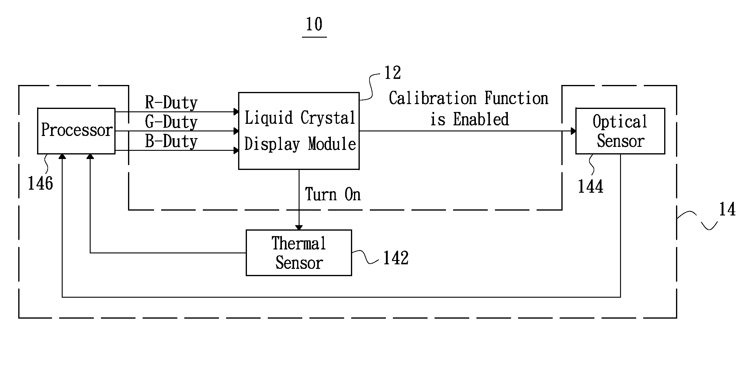
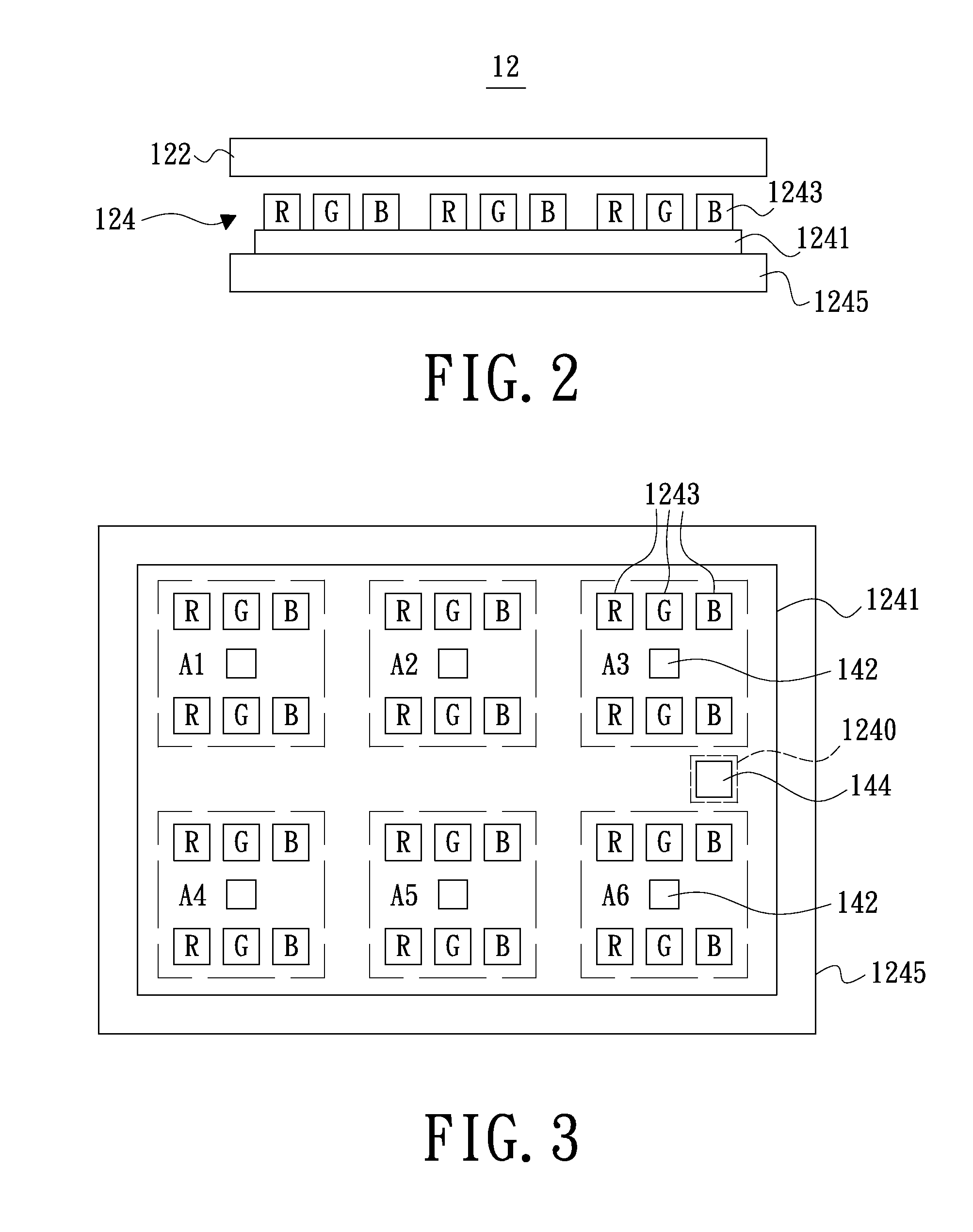
A driving apparatus and a driving method of a backlight module are provided. The backlight module includes multiple LEDs. The driving apparatus includes at least one thermal sensor, an optical sensor, and a processor. The thermal sensor is for detecting a working temperature of the LEDs. The optical sensor is for detecting brightness and color of the backlight module after a calibration function is enabled, to obtain difference values of the detected brightness and color with respect to predetermined brightness and color. The processor is for providing at least one initial thermal compensation table, to determine working currents of the LEDs associated with the working temperature. The processor further is for calibrating a content of the initial thermal compensation table corresponding with a current working temperature of the LEDs and storing the calibrated thermal compensation table as the initial thermal compensation table after the calibration function is enabled.

Description

CROSS-REFERENCE TO RELATED APPLICATIONS[0001]This application is based upon and claims the benefit of priority from the prior Taiwanese Patent Application No. 098111735, filed Apr. 8, 2009, the entire contents of which are incorporated herein by reference.BACKGROUND[0002]1. Technical Field[0003]The invention generally relates to driving apparatuses and driving methods of display devices, and more particularly to a driving apparatus and a driving method of a backlight module.[0004]2. Description of the Related Art[0005]In regard to a non-emissive display device such as a liquid crystal display, a backlight module is a main light source of the non-emissive display device. The luminescence characteristic and life-span of the light source generally have in-close relationship with the display quality and life-span of an end product. In order to meet the increasing demands for environmental protection, energy saving, colors as well as images, light emitting diodes have been widely used as...

Claims


Application Information

Patent Timeline
Patent Type & Authority Patents(United States)
IPC IPC(8): G09G3/36
CPCG09G3/3611G09G3/3413G09G2320/041G09G3/3426G09G2320/0626G09G2360/145
Inventor YANG, CHIAO-CHIHLIN, CHIH-HUACHOU, WEI-JENHSIAO, CHIEN-CHUNG
Owner CORETRONIC
Learn More