Image reading apparatus, image reading method and program

a reading apparatus and image technology, applied in the field of image reading apparatus, image reading method and program, can solve the problems of color misalignment, color misalignment, color misalignment, etc., and achieve the effect of not increasing the circuit scale or processing tim

Inactive Publication Date: 2014-04-29
CANON KK
View PDF17 Cites 2 Cited by
  • Summary
  • Abstract
  • Description
  • Claims
  • Application Information

AI Technical Summary

Benefits of technology

[0009]The present invention enables realization of an image reading apparatus, an image reading method and a program for favorably correcting color misalignment in the sub-scanning direction of read signals read by a plurality of line sensors, without increasing the circuit scale or processing time.

Problems solved by technology

However, there is a problem in that when an original document image is read by moving the line sensor or the original document, color misalignment occurs due to an effect from mechanical vibration that occurs in a driving mechanism for moving the line sensor or the original document in the sub-scanning direction, or feed accuracy.
In the line-sequential reading method, generally, the line sensor or an original document to be read is continuously moved during the reading operation, and thus the read positions of the R, G, and B light at the emission timing shift in the sub-scanning direction as described above, causing color misalignment to occur when an original document including characters, line images or the like is read.
However, the estimated read position and the actual read position are displaced from each other due to fluctuation in the moving speed in the sub-scanning direction, and as a result, color misalignment occurs.
However, the conventional techniques have problems described below.
Of course, the method can be realized without extending the reading time by increasing the operation speed of the color misalignment correction circuit two fold, but the apparatus cost will increase if a circuit configuration that supports such high-speed operation is realized, which is not preferable.
Furthermore, with the image reading method disclosed in Japanese Patent Laid-Open No. 2003-259135, although the method has a sufficient effect for black characters, no processing is performed with respect to the color misalignment in the contour portions of colored characters, the color misalignment in black characters on a chromatic color background, or the like.

Method used


Image

  • Image reading apparatus, image reading method and program
  • Image reading apparatus, image reading method and program
  • Image reading apparatus, image reading method and program

Examples


first embodiment

Configuration of Image Reading Apparatus

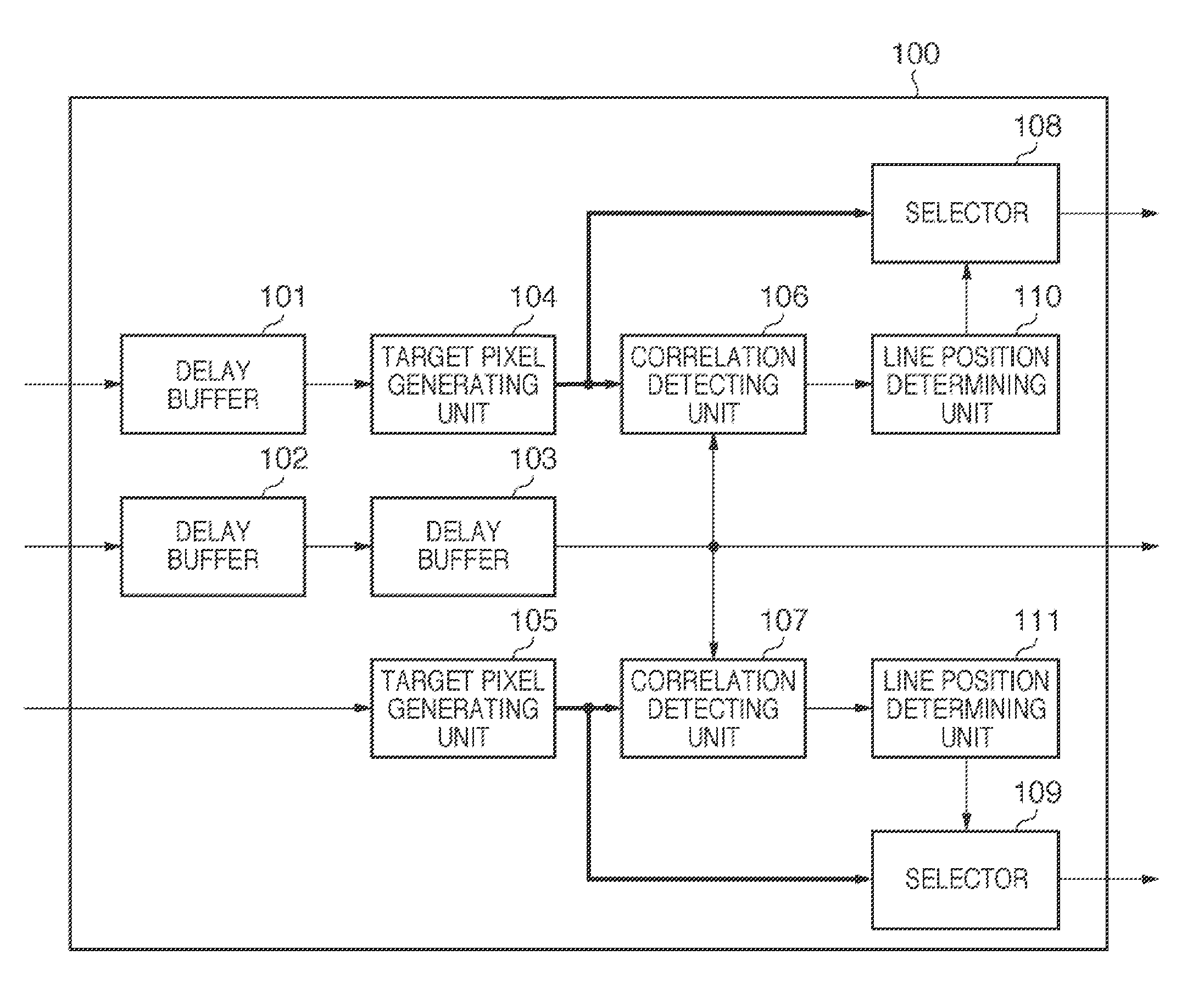
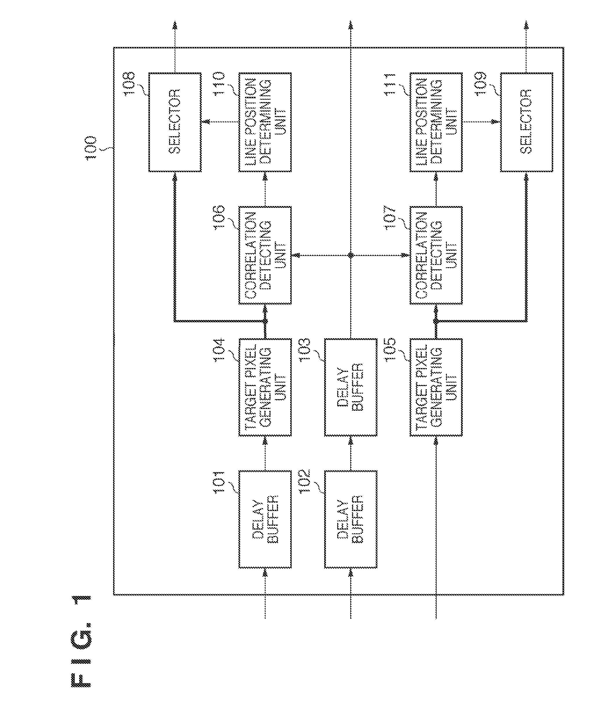
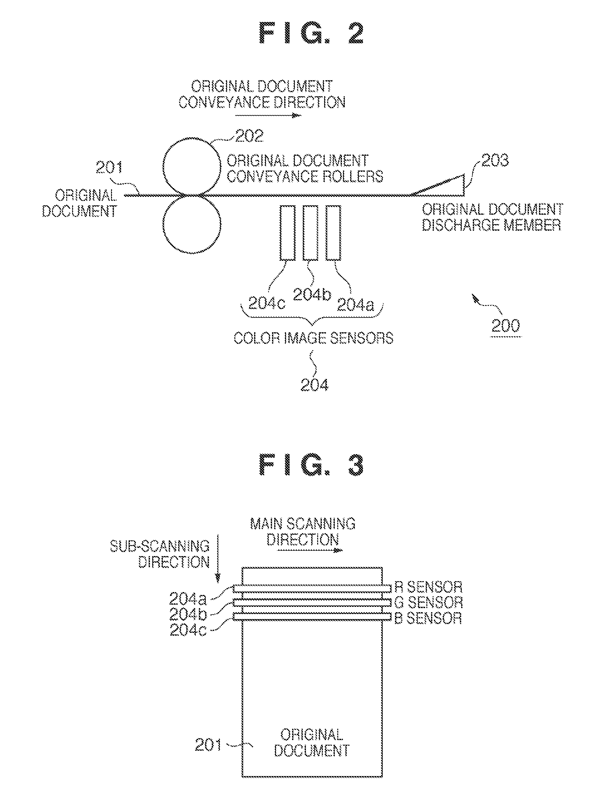
[0024]A first embodiment of the present invention will be described below with reference to FIGS. 1 to 5C. First, the main structure of the image reading unit in an image reading apparatus 200 will be described with reference to FIG. 2. An original document 201 to be read is conveyed by original document conveyance rollers 202, passes over an original document discharge member 203, and is discharged outside the image reading apparatus 200. Color image sensors 204 including an R sensor 204a, a G sensor 204b and a B sensor 204c are disposed between the original document conveyance rollers 202 and the original document discharge member 203, the R sensor 204a, the G sensor 204b and the B sensor 204c being disposed in different positions in the conveyance direction of the original document. Each sensor reads the corresponding color component amount of a conveyed original document 201 for each line, and outputs read signals. The present embodiment i...

second embodiment

[0046]Next, a second embodiment of the present invention will be described with reference to FIGS. 6 and 7. Note that in the description provided below, only portions different from the first embodiment will be described. Elements that are the same as those in the configuration of the first embodiment are given the same reference numerals. Firstly, an example of a color misalignment correction apparatus of the present embodiment will be described with reference to FIG. 6.

[0047]A large difference between the second embodiment and the first embodiment is the position of selectors 601 and 602. The selectors 601 and 602 each output, out of the target lines of the target pixel generating units 104 and 105, respectively, a two-line range starting from the line selected for the previous line. That is, the selectors 601 and 602 each function as a narrowing means for narrowing down the inputs from the target pixel generating units 104 and 105, respectively, and chooses the line to be employe...


PUM


Abstract

An image reading apparatus, an image reading method and a program are provided for favorably correcting color misalignment in a sub-scanning direction of a read signal read by a plurality of line sensors without increasing a circuit scale or processing time. To accomplish this, the image reading apparatus sets, as a reference signal, the read signal that is output from one of the plurality of line sensors, and detects a correlation between the reference signal and each of a plurality of read signals output from line sensors other than the one of the plurality of line sensors of a plurality of lines that are displaced in predetermined line units from a line from which the reference signal is read, and selects a read signal having a high correlation with the reference signal as a read signal from the line of the reference signal.

Description

TECHNICAL FIELD[0001]The present invention relates to an image reading apparatus, an image reading method and a program for correcting color misalignment that has occurred in color image data.BACKGROUND ART[0002]An image scanner that reads an original document as electronic image data includes a line sensor such as a CCD (Charge Coupled Device) or CIS (Contact Image Sensor), in which a plurality of light-receiving elements are linearly arrayed. The image scanner reads the original document image while moving the line sensor in a direction (sub-scanning direction) orthogonal to the array direction (main scanning direction) of the light-receiving elements. Alternately, there is an image scanner configured such that the line sensor is fixed and the original document is moved and the original document image is read.[0003]However, there is a problem in that when an original document image is read by moving the line sensor or the original document, color misalignment occurs due to an effe...

Claims


Application Information

Patent Timeline
Patent Type & Authority Patents(United States)
IPC IPC(8): G06K9/00H04N1/60G06K15/00H04N1/04H04N1/46
CPCH04N1/00023H04N1/1013H04N2201/0081H04N1/12H04N1/00068H04N1/193H04N1/00013H04N2201/04794H04N2201/04787H04N1/0473H04N2201/04703H04N1/0005H04N1/00063H04N2201/04743H04N2201/04734H04N1/00082
Inventor ISHIKAWA, HISASHI
Owner CANON KK
Why Eureka
Try Eureka