
System and method for supporting fibre channel over ethernet communication

a technology of ethernet communication and fibre channel, applied in the field of computer networks, can solve the problems of increasing the complexity of adapter configuration and the number of cables, increasing the amount and complexity of data that business and industry, and affecting the operation of the company. or completely stopping,

Active Publication Date: 2014-04-29
CHENGDU HUAWEI TECH
View PDF66 Cites 17 Cited by
  • Summary
  • Abstract
  • Description
  • Claims
  • Application Information

AI Technical Summary

Benefits of technology

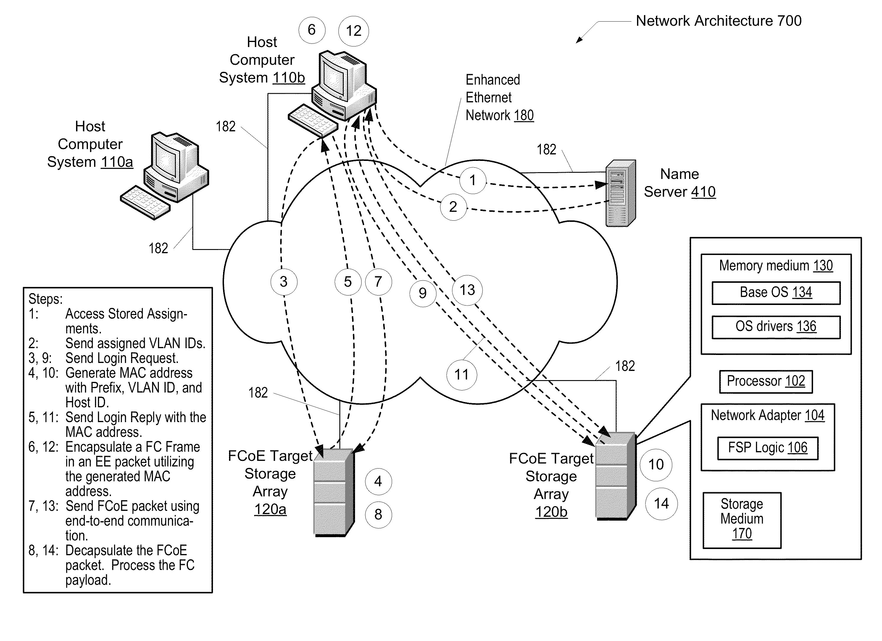
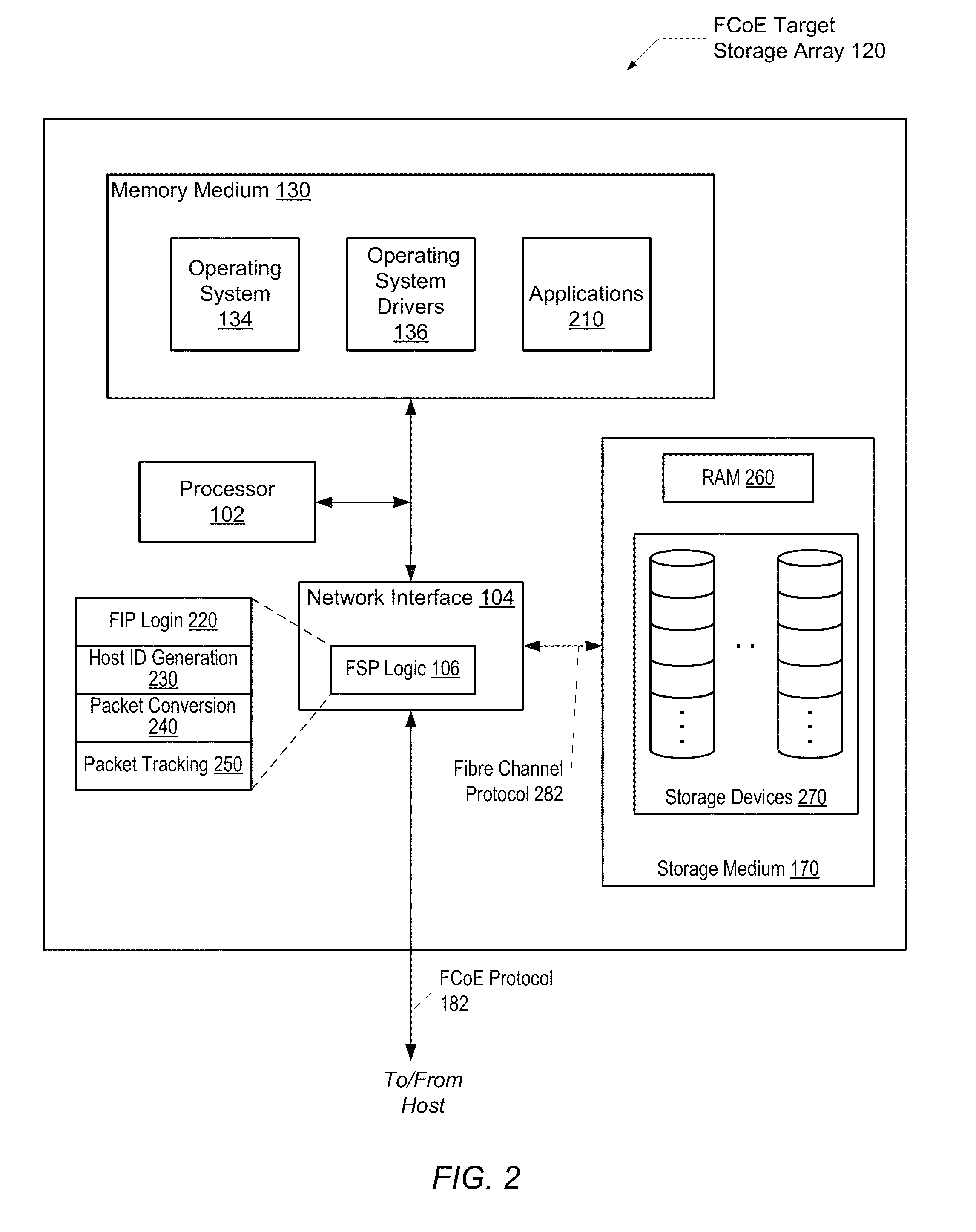
The patent describes a computer system and methods for transmitting packets over two different network protocols without protocol conversion in switches. In one embodiment, host computers are connected to a network through an enhanced Ethernet network, and target storage arrays are also connected. The host computers use a predefined network protocol to log in to the target storage arrays and assign unique identifiers to them. A virtual link is then established between the host computer and the target storage array for communication. The target storage array decapsulates received FCoE packets, accessing the stored data using the Fibre Channel protocol. Overall, this technology allows for seamless communication between the host computer and the target storage array without needing conversion in switches.

Problems solved by technology

As computer memory storage and data bandwidth increase, so does the amount and complexity of data that business and industry daily manage.
If any portion of the data center has poor performance or becomes unavailable, company operations may be impaired or stopped completely.
The complexity of adapter configurations and the number of cables both increase as the processor performance increases.
However, these changes both impact currently deployed FCoE initiators that adhere to the existing FC-BB-5 standard and / or utilize an expensive new FCF.

Method used


Image

  • System and method for supporting fibre channel over ethernet communication
  • System and method for supporting fibre channel over ethernet communication
  • System and method for supporting fibre channel over ethernet communication

Examples


Embodiment Construction

[0021]In the following description, numerous specific details are set forth to provide a thorough understanding of the present invention. However, one having ordinary skill in the art should recognize that the invention might be practiced without these specific details. In some instances, well-known circuits, structures, signals, computer program instruction, and techniques have not been shown in detail to avoid obscuring the present invention.

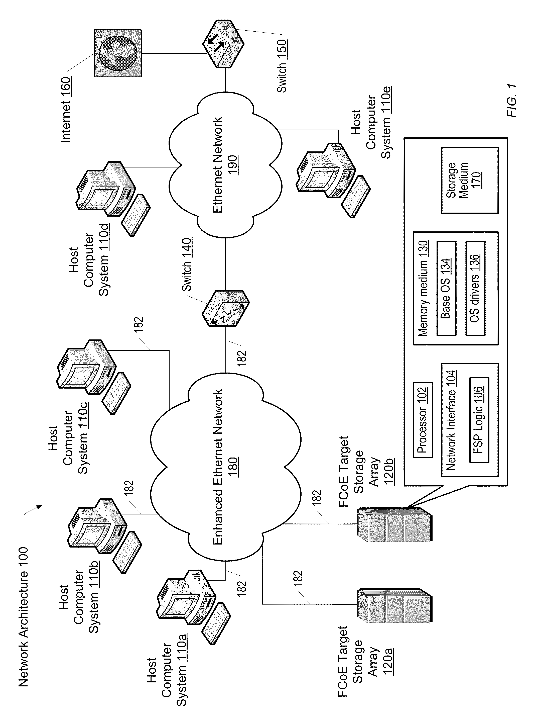
[0022]Referring to FIG. 1, one embodiment of network architecture 100 is shown. Network architecture 100 includes host computer systems 110a-110c interconnected through an enhanced Ethernet (EE) network 180 to one another and to Fibre Channel over Ethernet (FCoE) target storage arrays 120a-120b. Network 180 may be coupled to an Ethernet network 190 through an Ethernet switch 140. Host computer systems 110d-110e are interconnected through the Ethernet network 190. Network 190 may be coupled to the Internet 160 or other outside network through s...


PUM


Abstract

A system and method for transmitting packets over two different network protocols without protocol conversion in any switches. A computer system comprises host computers and target storage arrays, or targets, coupled to one another through a Enhanced Ethernet network. Each of the host computers and the targets is configured to transmit encapsulated packets, such as a Fiber Channel over Ethernet (FCoE) packet. During system configuration, each of the targets is set to be the only target included in a virtual local area network (VLAN) with a corresponding unique VLAN identifier (ID). A given host computer logins to multiple assigned targets using a predefined Fiber Channel protocol. In response to a login request, a corresponding target assigns and conveys a N_Port ID that comprises a VLAN ID and a unique Host ID to the host computer in a reply message. A virtual link is established between the host computer and the target storage array.

Description

BACKGROUND OF THE INVENTION[0001]1. Field of the Invention[0002]This invention relates to computer networks and, more particularly, to transmitting packets over two different network protocols without protocol conversion in any switches.[0003]2. Description of the Related Art[0004]As computer memory storage and data bandwidth increase, so does the amount and complexity of data that business and industry daily manage. Businesses typically rely on data centers to run many operations. A data center generally includes client or host computers interconnected by one or more networks. The host computers increasingly share one or more data storage subsystems via the one or more networks. If any portion of the data center has poor performance or becomes unavailable, company operations may be impaired or stopped completely. A data center must therefore keep high standards for assuring the integrity and functionality of its hosted computer environment.[0005]A data center may utilize two or mor...

Claims


Application Information

Patent Timeline
Patent Type & Authority Patents(United States)
IPC IPC(8): H04L12/28
CPCH04L12/4641H04L12/4633H04L49/357H04L12/28
Inventor KO, MICHAEL
Owner CHENGDU HUAWEI TECH
Learn More