
Optimizer for two staged refrigeration systems

a refrigeration system and stage technology, applied in the field of two staged refrigeration systems, can solve the problems of high energy consumption, high cost of compressor replacement and other necessary repairs, and the system is not implemented in the millions of already existing refrigeration systems, and achieves the effects of reducing inrush current, reducing noise, and stable motor winding temperatur

Inactive Publication Date: 2014-05-06
LIU MINGSHENG
View PDF7 Cites 1 Cited by
  • Summary
  • Abstract
  • Description
  • Claims
  • Application Information

AI Technical Summary

Benefits of technology

[0012]Accordingly, it is one aspect of an embodiment of the present invention to integrate the modulation and control devices for the indoor fan and compressor into a single, more cost efficient optimizer that can be readily implemented in new and existing two staged refrigeration systems in settings including but not limited to residential air conditioning systems, residential and commercial heat pump systems, water source heat pump systems, and roof top units.
[0014]It is a further aspect of an embodiment of the present invention to prevent liquid sludge related compressor damage as well as minimize motor failure.
[0015]It is yet a further aspect of an embodiment of the present invention to maintain adequate humidity control, thermal comfort levels, maintenance and repairs, and eliminate short cycling in both new and existing refrigeration systems.
[0017]The controller identifies possible faults including (but not limited to) issues involving low charge in the compressor, compressor leakage, dirty coils, and fan belt loss. Since system faults are reported and detected, there is a reduction in compressor and fan failure rates, on and off cycling rates, and O&M costs. Starting the compressor at a low speed maintains a stable motor winding temperature and reduces the inrush current by more than half. Further, motor failure is minimized and liquid sludge related compressor damage prevented. The optimizer applies (but is not limited) to rotary, scroll, screw, and reciprocating compressors. Compressor noise is also reduced under partial load conditions.
[0018]Notably, the method and system disclosed herein provides a feasible solution for retrofitting existing systems or those systems that are currently implemented in approximately over 50% of building spaces. However, the optimizer can also be implemented in new systems as well. Due to an energy penalty when moisture is removed from a building, the higher the already existing relative humidity levels, the lower the expected percent energy savings. The optimizer can help reduce peak demand by approximately 30% to 70% depending on the sizing and over-sizing of existing systems. It may also increase system energy by approximately 50%, and reduce energy consumption rates by approximately 20% to 50% according to the seasonal load profile and existing room humidity conditions.

Problems solved by technology

Yet because cooling loads and heating loads vary substantially over the operative spectrum, these measures did not solve the excessive indoor humidity and noise levels, high energy consumption rates, and the high cost of compressor replacements and other necessary repairs often associated with the refrigeration systems.
Due to high retrofit costs, however, this system is not implemented in the millions of already existing refrigeration systems.
Noise levels are still high under partial load conditions as well.
Results from lab experiments conducted by the inventor of the proposed application suggests that modulating the condenser fan at the same speed as the compressor and indoor fan will result in a 20+ energy penalty under most operating conditions.

Method used


Image

  • Optimizer for two staged refrigeration systems
  • Optimizer for two staged refrigeration systems
  • Optimizer for two staged refrigeration systems

Examples


Embodiment Construction

[0035]The particular values and configurations discussed in these non-limiting examples can be varied and are cited merely to illustrate an example of at least one embodiment of the present invention and are not intended to limit the scope of the invention. Also, it is understood that the phraseology and terminology used herein is for the purpose of description and should not be regarded as limiting. The use of “including,”“comprising,” and variations thereof herein is meant to encompass the items listed thereafter and equivalents thereof as well as additional items. Unless specified or limited otherwise, the terms “mounted,”“connected to,”“attached to,” and variations thereof are used broadly to encompass both direct and indirect mountings, connections, and supports.

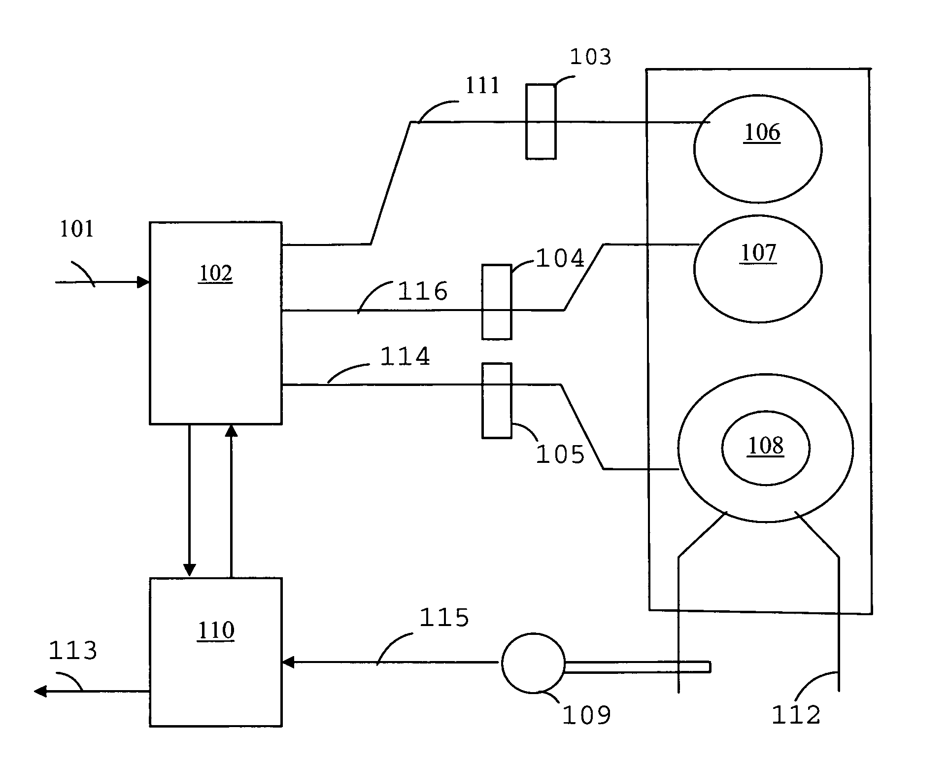
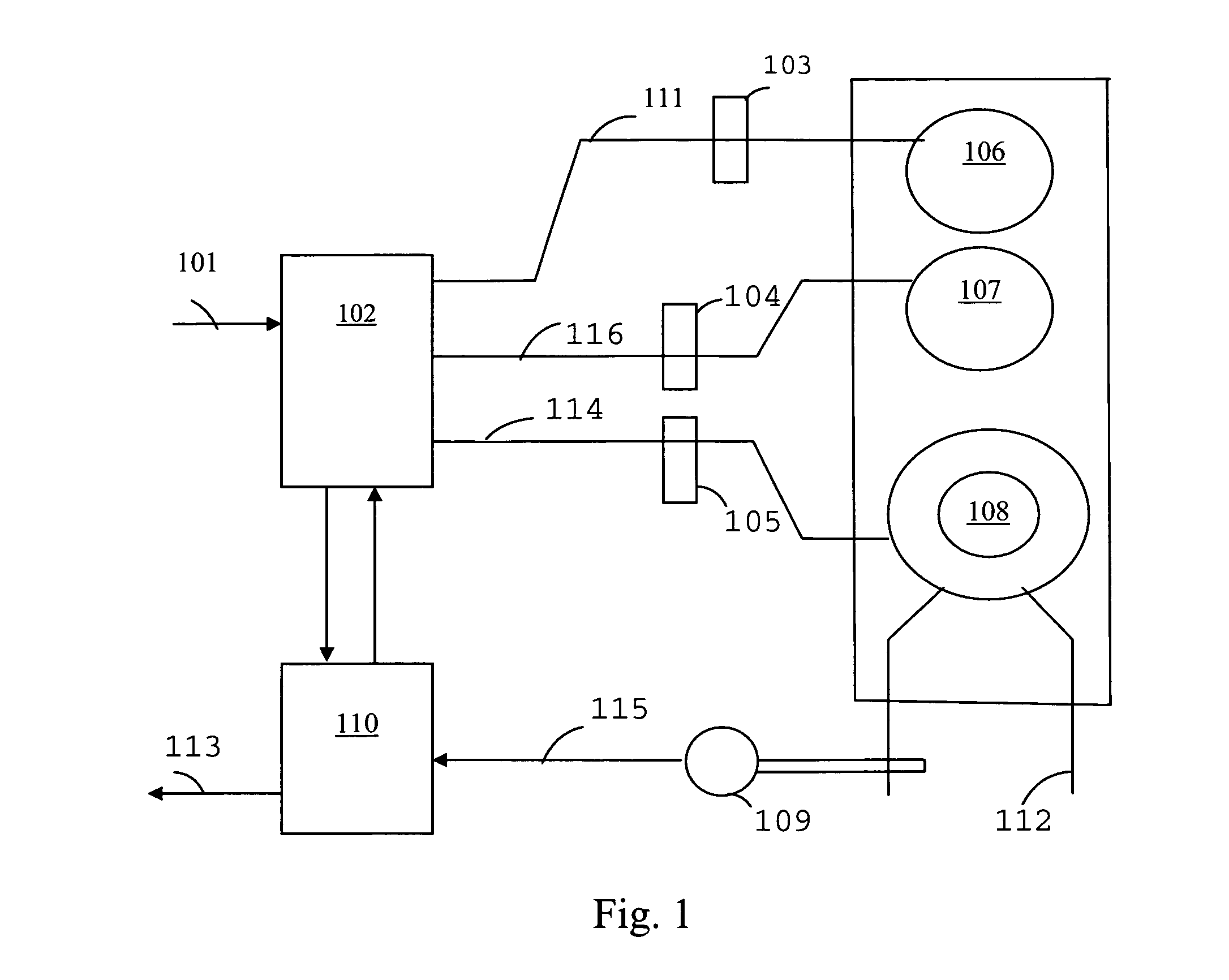
[0036]FIG. 1 shown below illustrates an embodiment of an optimizer for use in a two staged refrigeration system. Power for running the optimizer is derived from existing power source 101, which can be either single or t...


PUM


Abstract

An optimizer for modulating the speed of an indoor fan and first and second stage compressors of a two staged refrigeration system with a plurality of relays and an already existing power source. The optimizer is comprised of a speed modulation device, a supply air temperature sensor, and a controller. The speed modulation device is located in proximity to the existing power source and configured to collect current and power related information from the refrigeration system and power source to send to the controller. The supply air temperature sensor is linked to the indoor fan of the two staged refrigeration system and operable to obtain supply air temperature values. The controller is linked in communication with the speed modulation device and supply air temperature sensor and is operable to generate a system mode based on the power, current, and supply air temperature information. Speed commands are then sent to the speed modulation device to modulate the speed.

Description

CROSS-REFERENCE TO RELATED APPLICATIONS[0001]This application is related to U.S. patent application Ser. No. 12 / 653,382 entitled “Optimizer for Single Staged Refrigeration Systems”.STATEMENT REGARDING FEDERALLY SPONSORED RESEARCH OR DEVELOPMENT[0002]Not ApplicableREFERENCE TO SEQUENCE LISTING, A TABLE, OR A COMPUTER PROGRAM LISTING COMPACT DISC APPENDIX[0003]Not ApplicableBACKGROUND OF THE INVENTION[0004]1. Technical Field[0005]Embodiments are generally related to two staged refrigeration systems, and more particularly to two staged refrigeration systems used in but not limited to residential air conditioning systems, roof top units, residential and commercial air source heat pumps, and water source heat pumps.[0006]2. Discussion of Prior Art[0007]Two staged refrigeration systems are widely used in both residential and commercial buildings. Typical systems maintain single zone room temperatures by staging one or more compressors on and off in two stages. Two staged refrigeration sys...

Claims


Application Information

Patent Timeline
Patent Type & Authority Patents(United States)
IPC IPC(8): G01M1/38F25B1/00G01R19/00
CPCF25B49/022F25B2700/21Y02B30/741F25B1/10F25B2600/0253F25B2600/11F25B2700/15Y02B30/70
Inventor LIU, MINGSHENG
Owner LIU MINGSHENG
Learn More