Turf aerator

a technology of which is applied in the field of man-foot-operated turf aerating machines and mechanisms, can solve the problems of lack of any component or structure for assistance in upward pulling of tines, lack of versatility in use of aerators, and lack of commonly known and configured foot-actuated turf aerating machines

Active Publication Date: 2014-05-06
NG YEOW
View PDF39 Cites 5 Cited by
  • Summary
  • Abstract
  • Description
  • Claims
  • Application Information

AI Technical Summary

Benefits of technology

[0009]Upon reaching a desired location for commencement of lawn aeration, the user may tilt the turf aerator forwardly to cause the lower ends of the tines to contact the turf, such tilting motion preferably progressing until the tines are substantially perpendicular with the turf. Thereafter, the user, while grasping the “U” member's handle, may move the lower portion and foot of one of his or her legs between the “U” member's left and right arms. Thereafter, the user may step downwardly with such extended foot upon the rigid plate's upper surface, driving the plate downwardly toward the turf, and simultaneously driving the left and right tines downwardly into the turf. While such foot driving action occurs, the upwardly extending “U” member lever arm advantageously assists the user, who at that instant stands with one foot upon the ground, to remaining in balance and standing, while allowing the user to maintain the desired perpendicular orientation of the tines. Following execution of the foot actuated downward driving steps described above, the user may step back slightly from the turf aerator and may pull rearwardly upon the handle. Such pulling action advantageously causes the “U” member handle to function as a lever arm with respect to the rearwardly extending left and right wheels which function as a fulcrum. Upon such levering, the forwardly extending rigid plate simultaneously acts as a counter-lever arm which pulls the tines upwardly and out of the turf. Performance of a multiplicity of repetitions of the steps described above effectively aerates the user's lawn surface.

Problems solved by technology

Commonly known and configured foot actuated turf aerating machines lack versatility in their use upon and within lawn and landscaping maintenance environments.
For example, lawn aerating machines which present structures for facilitating foot driven aerating tine actuation often lack any component or structure for assistance in upward withdrawals of the tines.
Also, such common aerators lack versatility in use in the lawn environment, they having capabilities limited to lawn turf aeration.

Method used


Image

  • Turf aerator
  • Turf aerator
  • Turf aerator

Examples


Embodiment Construction

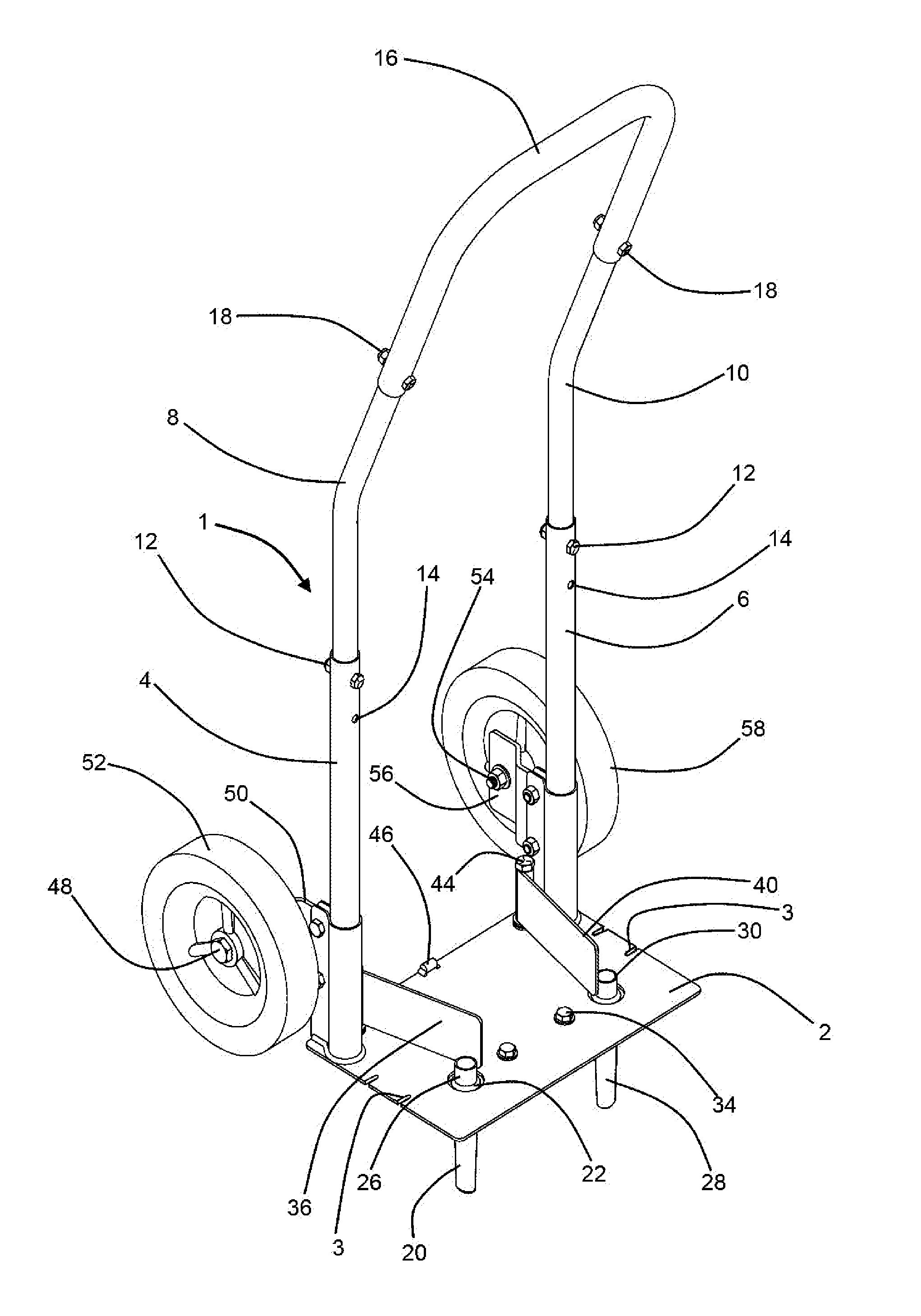
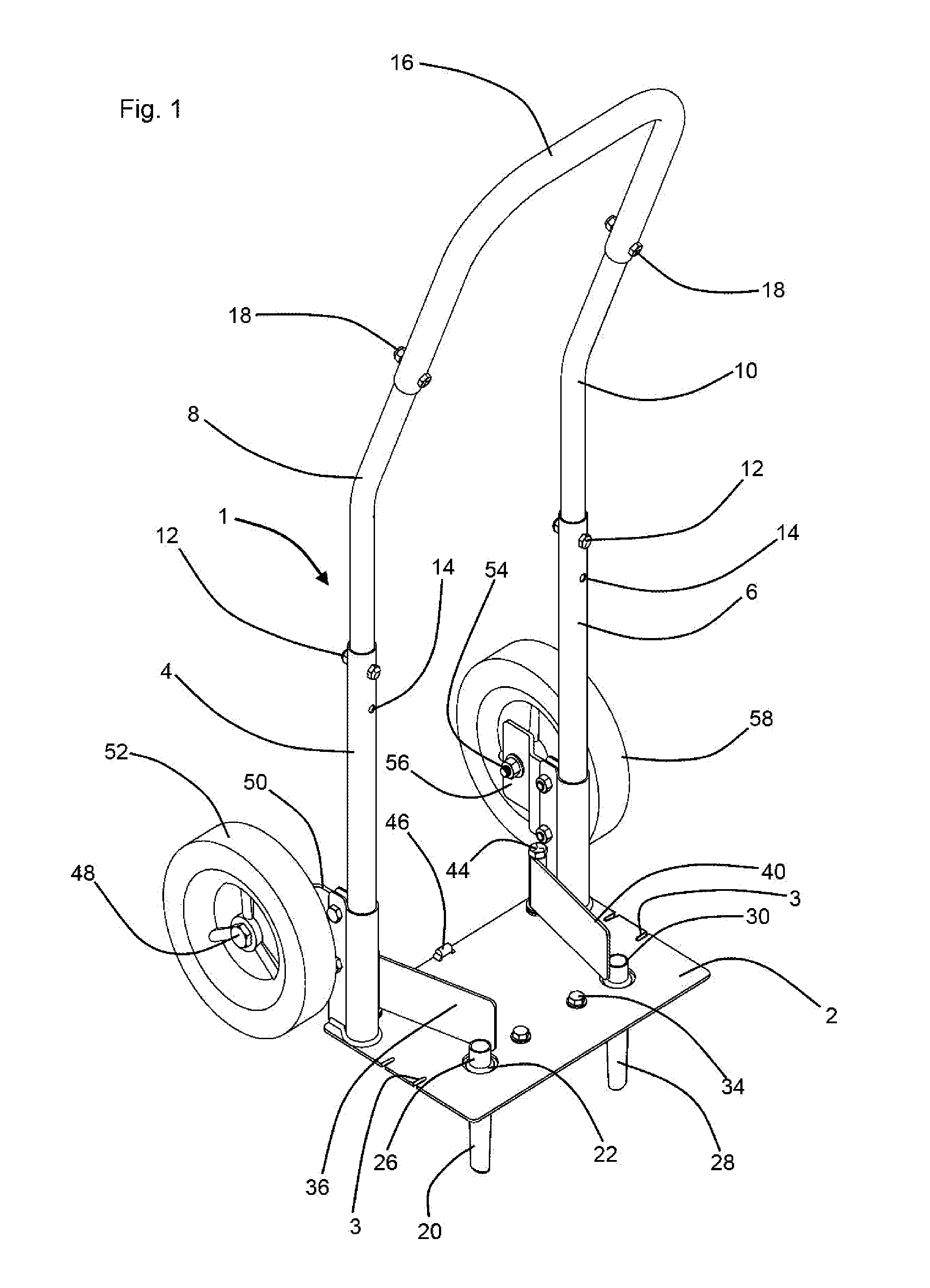
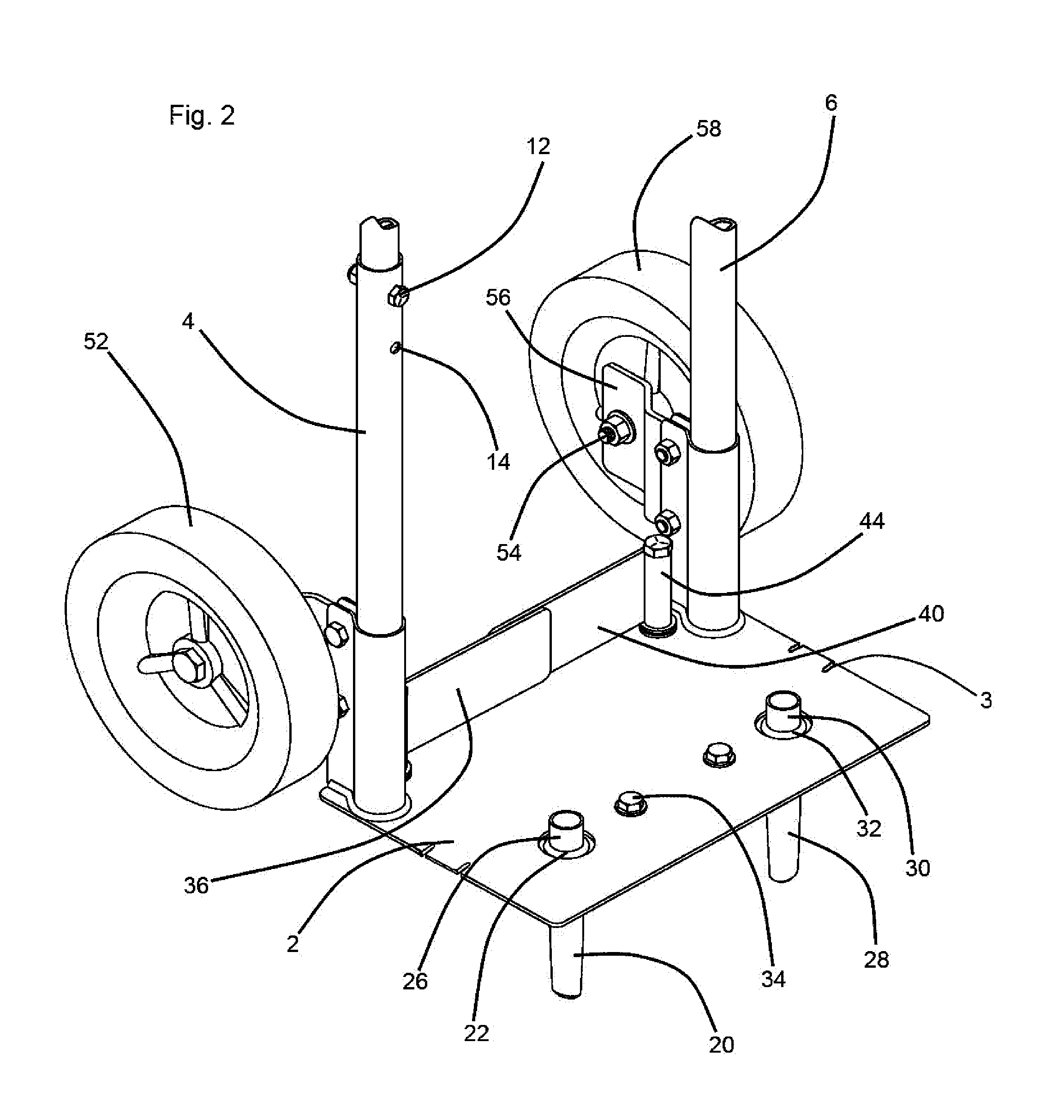
[0022]Referring now to the drawings, and in particular to FIG. 1, a preferred embodiment of the instant inventive turf aerator is referred to generally by Reference Arrow 1. The turf aerator 1 preferably comprises a rigid, rectangular, and laterally oblongated foot plate 2. The foot plate 2 preferably has a pair of or left and right tine head receiving apertures 22 for receiving the upper ends or heads 30 and 26 of turf coring tines 28 and 20. While such tine pair is preferred, the scope of the invention is considered to include utilization of fewer or a greater number of tines. Referring further simultaneously to FIG. 3, the tines 28 and 20 preferably extend through and are welded upon a laterally extending the mounting plate 35. A plurality of nut and bolt combinations 34 preferably extend through apertures (not depicted within views) within plate 35, and through overlying apertures (also not depicted within views) within foot plate 2, such fasteners securely mounting the turf cor...


PUM


Abstract

A turf aerator comprising a foot plate having an upper surface, a lower surface, a front end, a rearward end, a left side, and a right side; at least a first turf coring tine fixedly attached to and extending downwardly from the foot plate; a lever arm fixedly attached to and extending upwardly from the foot plate; and a ground contacting fulcrum fixedly attached to and extending rearwardly from the foot plate.

Description

FIELD OF THE INVENTION[0001]This invention relates to manual and foot operable turf aerating machines and mechanisms. More particularly, this invention relates to such turf aerating machines and mechanisms which are operable for aerating tine driving via foot action and for withdrawals of such tines via hand operated lever action.BACKGROUND OF THE INVENTION[0002]Commonly known and configured foot actuated turf aerating machines lack versatility in their use upon and within lawn and landscaping maintenance environments. For example, lawn aerating machines which present structures for facilitating foot driven aerating tine actuation often lack any component or structure for assistance in upward withdrawals of the tines. Also, such common aerators lack versatility in use in the lawn environment, they having capabilities limited to lawn turf aeration.[0003]The instant inventive turf aerator solves or ameliorates problems such as those discussed above by providing a turf aerating machine...

Claims


Application Information

Patent Timeline
Patent Type & Authority Patents(United States)
IPC IPC(8): A01B45/02
CPCA01B1/243A01B45/02
Inventor NG, YEOW
Owner NG YEOW
Why Eureka
Try Eureka