Adjustable Wrench

a wrench and adjustment technology, applied in the field of adjustable wrenches, can solve the problems of distorted springs and fatigue, and achieve the effect of quick turning of objects and large torqu

Inactive Publication Date: 2013-09-26
NEW WAY TOOLS
View PDF5 Cites 5 Cited by
  • Summary
  • Abstract
  • Description
  • Claims
  • Application Information

AI Technical Summary

Benefits of technology

[0012]It is therefore an objective of the present invention to provide an adjustable wrench for quickly turning an object and usable in a circumstance which requires a relatively large torque to turn the object.
[0013]It is another objective of the present invention that the first and second springs set forth above better assist relative movements of the handle with respect to the driving head, and they will not become distorted easily.

Problems solved by technology

Unfortunately, the spring becomes fatigue and distorted after repetitive movements of driving head with respect to the handle.

Method used


Image

  • Adjustable Wrench
  • Adjustable Wrench
  • Adjustable Wrench

Examples


Embodiment Construction

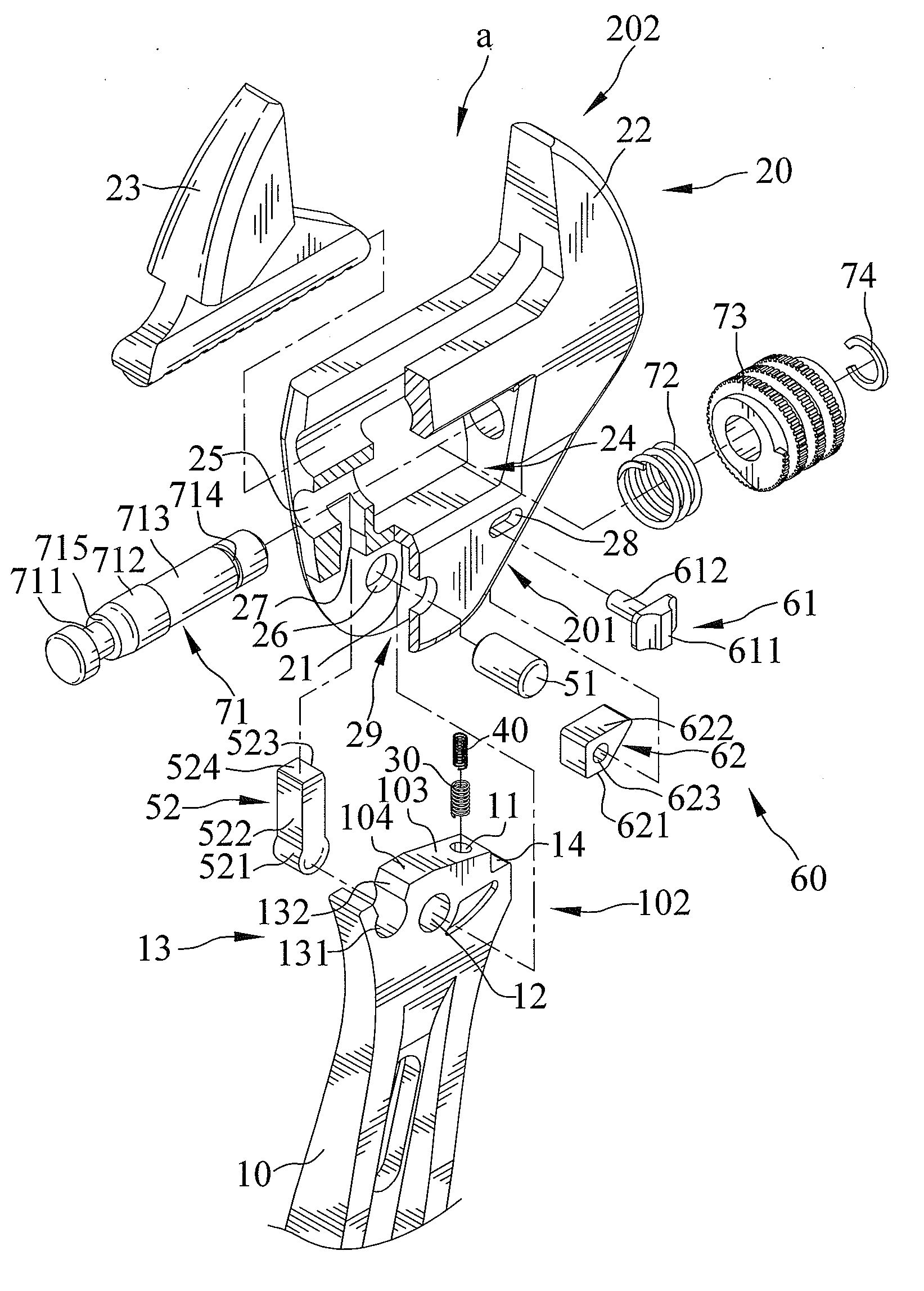
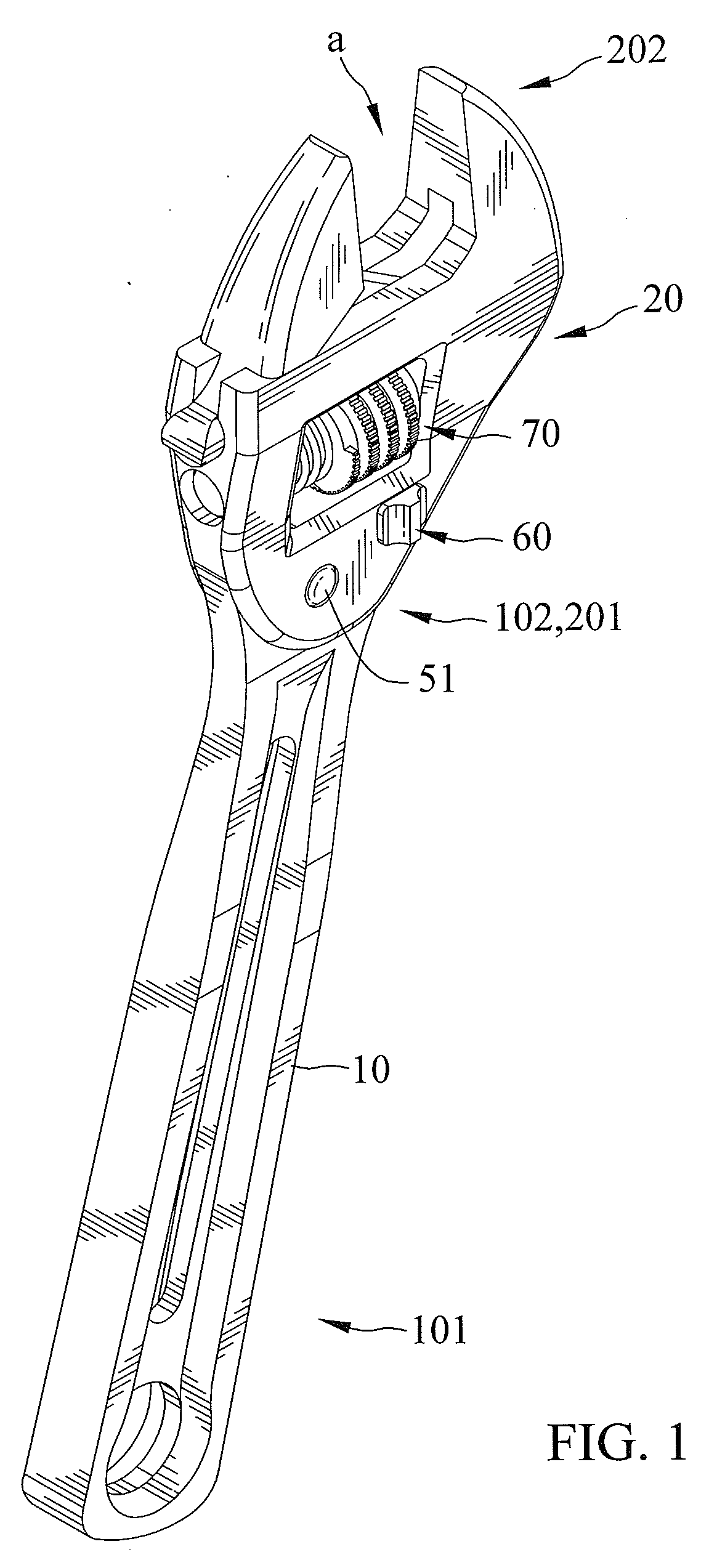
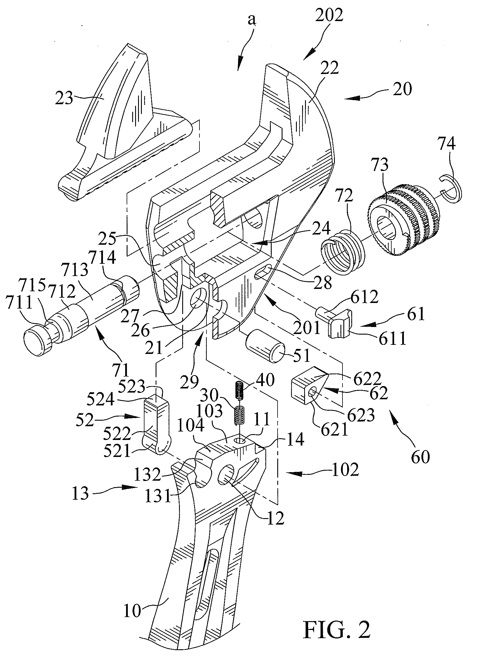
[0027]FIGS. 1 through 12 show an adjustable wrench in accordance with a first embodiment of the present invention. The adjustable wrench includes a handle 10, a driving head 20, a first spring 30, and a second spring 40.

[0028]The handle 10 for a user to grasp when operating the adjustable wrench has an outer periphery thereof including a notch 11 defined therein. The handle 10 defines a grasping end 101 and a connecting end 102. The handle 10 has the outer periphery defining an abutting edge which defines a first abutting surface 103 and a second abutting surface 104 and includes the notch 11 defined therein. The first abutting surface 103 is oblique to the second abutting surface 104. The handle 10 also includes a first orifice 12 and a concavity 13 and a recess 14 defined therein. The concavity 13 is defined on the connecting end 102 of the handle 10. The concavity 13 has an arcuate section 131 and two inclined section 132 extended from two distal ends of the arcuate section 131, ...


PUM


Abstract

An adjustable wrench includes a handle including a notch defined therein. A driving head is pivotally fixed to the handle for engaging an object that is driven by the adjustable wrench. The driving head and the handle include first and second springs engaged therebetween. The first and second springs each include a first end abutting against the handle and a second end abutted against the driving head, respectively. The notch receives the first and second springs. Coils of the second spring are disposed within a space delimited by coils of the first spring. One of the first and second springs is coiled clockwise from the first end to the second end thereof, and the other of the first and second springs coiled counterclockwise from the first end to the second end thereof.

Description

BACKGROUND OF THE INVENTION[0001]1. Field of the Invention[0002]The present invention relates to an adjustable wrench and, in particular, to an adjustable wrench for quickly turning an object.[0003]2. Description of the Related Art[0004]U.S. Pat. No. 6,336,384 shows an adjustable wrench for quickly turning an object. The adjustable wrench includes a handle and a driving head pivotally connected together. A spring is installed between the handle and the driving head. The handle and the driving head can reciprocally pivot with each other, and the spring is selectively depressed and released by the driving head and the handle. Thereby, the spring aids the driving head to reciprocally pivot with respect to the handle. Unfortunately, the spring becomes fatigue and distorted after repetitive movements of driving head with respect to the handle.[0005]The present invention is, therefore, intended to obviate or at least alleviate the problems encountered in the prior art.SUMMARY OF THE INVEN...

Claims


Application Information

Patent Timeline
Patent Type & Authority Applications(United States)
IPC IPC(8): B25B13/16
CPCB25B13/14B25B13/46B25B13/16
Inventor HUANG, PING-WEN
Owner NEW WAY TOOLS
Why Eureka
Try Eureka