Nanostructures formed of branched nanowhiskers and methods of producing the same

a technology of nanowhiskers and nanostructures, which is applied in the field of nanostructures formed of branched nanowhiskers and methods of producing the same, can solve the problems of yielding and achieve the effect of more complex “tree” structures

Inactive Publication Date: 2010-02-16
QUNANO
View PDF13 Cites 8 Cited by
  • Summary
  • Abstract
  • Description
  • Claims
  • Application Information

AI Technical Summary

Benefits of technology

[0016]The present invention provides, in one of its main aspects, a nanostructure having a novel tree-like construction formed of nanowhiskers, and methods of producing such a nanostructure. Generally, the tree-like structure includes a base nanowhisker, which may be analogized to the trunk of a tree, and one or more nanowhiskers grown outwardly from a peripheral surface of the base nanowhisker and analogous to branches of a tree. Additional nanowhisker “branches” may be grown upon the periphery of one or more previously grown nanowhisker branches, yielding more complex “tree” structures. The base nanowhisker may be formed in any desired manner, but is preferably grown on a substrate by the VLS mechanism so as to be upstanding from the substrate. Branch nanowhiskers are also preferably formed by the VLS mechanism, at intermediate points along the length of the base nanowhisker or, in the case of a nanowhisker grown on a previously grown branch, at an intermediate point along the length the previously grown branch. Constituent materials and growth parameters of the nanowhiskers may be controlled so as to achieve structures having desired form and characteristics. Self-assembly techniques may advantageously be used to form novel structures and devices incorporating large numbers of tree-like nanostructures.
[0027]It has been found that by application of electric voltages to the substrate, electric fields created around the nanowhiskers greatly assist in electrostatic precipitation of the nanoparticles on to the existing grown nanowhiskers. Thus said second catalytic particles are preferentially deposited on the sides of the first nanowhiskers, as opposed to the substrate. Although there may be some deposition randomly on the substrate, the high electric fields created around the nanowhiskers will cause preferential deposition on the nanowhiskers. More generally, the nth catalytic particle deposition (n being a positive integer greater than or equal to 2) is preferentially deposited on the (n−1)th growth of nanowhiskers, although some deposition on the (n−2)th growth, etc., may also occur for a third or subsequent particle deposition. Further, it has been found that the catalytic particles are evenly distributed circumferentially of the existing nanowhiskers and along the length of the nanowhiskers by appropriate control of the aerosol deposition.
[0042]In one specific application of structures formed from nanostructures according to the invention, a solar cell array is constructed, wherein at least some of said catalytic particles are employed as electrical contacts for applying a voltage between the free ends of the nanowhiskers and the substrate, permitting photoelectrons, released within the nanowhiskers by photon capture, to be swept away as electrical current. Junctions and heterojunctions between dissimilar materials created within and between nanowhiskers form convenient photodetector regions. Further the use of regions of dissimilar materials may permit the solar cell array to be sensitive to a variety of different wavelength regions, and thus make it more efficient.

Problems solved by technology

Additional nanowhisker “branches” may be grown upon the periphery of one or more previously grown nanowhisker branches, yielding more complex “tree” structures.

Method used


Image

  • Nanostructures formed of branched nanowhiskers and methods of producing the same
  • Nanostructures formed of branched nanowhiskers and methods of producing the same
  • Nanostructures formed of branched nanowhiskers and methods of producing the same

Examples


example

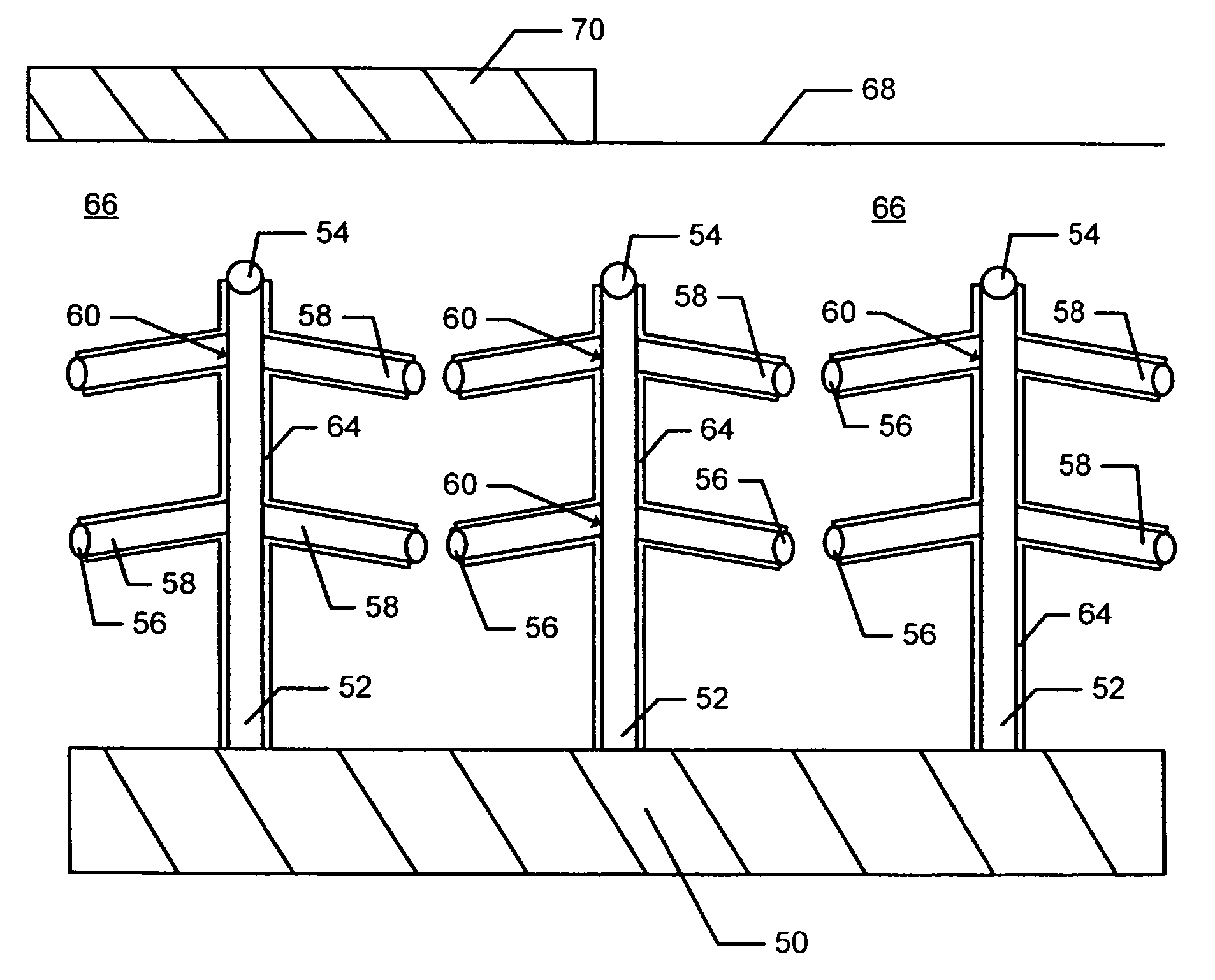
[0057]Growth of nanostructures comprising branched nanotrees was performed in two steps. The first was the growth of vertical GaP nanowires to serve as “trunks.” These were grown by the vapor-liquid-solid (VLS) mechanism. Gold seed particles were deposited on GaP (111)B substrate (˜10 mm2) by aerosol deposition, at a density of 0.5 particles per square micron of substrate. To achieve this, gold was evaporated in a high temperature (1850° C.) furnace, then passed through a charger to obtain a uniform charge distribution. Then, electrical mobility can be directly associated with size, and so particles are size-selected using a differential mobility analyser (DMA). Next, particles were re-heated (600° C.) to sinter (within the aerosol system), resulting in a compact, spherical shape, then size-selected a second time. As the selected particles thus have a uniform size and are singly charged, the total particle concentration can be determined by measuring the current from particles impin...


PUM

PropertyMeasurementUnit
thicknessaaaaaaaaaa
temperatureaaaaaaaaaa
lengthaaaaaaaaaa

Abstract

A method of forming a nanostructure having the form of a tree, comprises a first stage and a second stage. The first stage includes providing one or more catalytic particles on a substrate surface, and growing a first nanowhisker via each catalytic particle. The second stage includes providing, on the periphery of each first nanowhisker, one or more second catalytic particles, and growing, from each second catalytic particle, a second nanowhisker extending transversely from the periphery of the respective first nanowhisker. Further stages may be included to grow one or more further nanowhiskers extending from the nanowhisker(s) of the preceding stage. Heterostructures may be created within the nanowhiskers. Such nanostructures may form the components of a solar cell array or a light emitting flat panel, where the nanowhiskers are formed of a photosensitive material. A neural network may be formed by positioning the first nanowhiskers close together so that adjacent trees contact one another through nanowhiskers grown in a subsequent stage, and heterojunctions within the nanowhiskers create tunnel barriers to current flow.

Description

CROSS-REFERENCE TO RELATED APPLICATIONS[0001]This application claims the benefit of the priority of U.S. Provisional Patent Application No. 60 / 524,890 filed Nov. 26, 2003, the entirety of which is incorporated herein by reference, and of U.S. Provisional Patent Application No. 60 / 560,701 filed Apr. 9, 2004, the entirety of which is incorporated herein by reference.BACKGROUND OF THE INVENTION[0002]1. Field of the Invention[0003]This invention relates generally to methods of producing structures and devices by use of techniques of nanotechnology. More specifically, but not exclusively, the invention relates to methods of producing nanostructures incorporating at least one element, essentially in one-dimensional form, and that is of nanometer dimensions in its width or diameter. For the purposes of this application, such an element will be termed a “nanowhisker”. The invention also relates to structures and devices incorporating nanowhiskers, preferably produced by the so-called Vapor-...

Claims


Application Information

Patent Timeline
Patent Type & Authority Patents(United States)
IPC IPC(8): C30B29/62B82B1/00B82B3/00C30B11/00C30B11/12H01L33/18
CPCB82Y20/00B82Y30/00C30B11/12C30B29/40C30B29/44C30B29/605C30B29/62H01L21/02392H01L21/02433H01L21/02543H01L21/02603H01L21/0262H01L21/02639H01L21/02645H01L21/02653H01L31/035236H01L31/03529B01J37/0238B01J21/185Y10T428/25H01L31/101H01L33/18H01L33/20H01L33/24Y02E10/50Y10S977/89Y10S977/891Y10S438/962Y10S438/96Y10S977/754Y10S977/921B82B1/00B82B3/00C30B11/00C30B29/00
Inventor SAMUELSON, LARS IVARDEPPERT, KNUT WILFRIED
Owner QUNANO
Why Eureka
Try Eureka