LED light source and manufacturing method thereof

a technology of led light source and manufacturing method, which is applied in the direction of semiconductor devices for light sources, light and heating apparatus, planar light sources, etc., can solve the problems of led heat dissipation, conventional structures that fail to solve the problem of heat dissipation satisfactorily, and complicated cooling fan devices with relative low reliability, etc., to achieve the effect of enhancing heat dissipation and eliminating heat acumination

Active Publication Date: 2014-05-06
CAI ZOU
View PDF1 Cites 3 Cited by
  • Summary
  • Abstract
  • Description
  • Claims
  • Application Information

AI Technical Summary

Benefits of technology

[0009]Another advantage of the invention is to provide a LED member which can emit lights at both sides thereof that eliminates the heat acumination at the bonded surface and the substrate of the conventional LED light source.
[0010]Another advantage of the invention is to provide a LED member which is sandwiched between two fluorescent members to define one or more passage openings through which direct that heat transfer from the LED member through the passage opening is achieved.
[0011]Another advantage of the invention is to provide a two-layered LED member which is directly bonded with two fluorescent members in a sandwich manner which defines one ore more passage openings through which direct that heat transfer from the LED member through the passage opening is achieved.
[0012]Another advantage of the invention is to provide a three-layered LED member which is sandwiched between two fluorescent members that defines one or more passage openings through which direct that heat transfer from the LED member through the passage opening is achieved.
[0013]Another advantage of the invention is to provide a LED member which is sandwiched by two fluorescent members and bonded into position to define a LED receiving cavity with one or more passage openings, that a filled gas such as an inert gas is used to fill the receiving cavity for further enhance heat dissipation.
[0014]Another advantage of the invention is to provide a LED light bulb including a shell body defining a shell cavity which is filled with an inert gas to receive and communicate with at least one LED member or LED light source arrangement in such a manner that heat dissipation through the entire shell body is made possible.

Problems solved by technology

The cooling fan device is complicated but of relative low reliability.
All these conventional structures fail to solve the problem of heat dissipation satisfactorily.
Recently, the problem of LED heat dissipation is one of the major issues in developing LED into the modern light source.
In additional, the conventional LED light source only provides one light emitting surface while the other bonded surface is limited onto the substrate and cannot be used, resulting in a relatively low lighting intensity and efficiency.
Moreover, the light beams at the bonded surface are blocked by the substrate to emit and thus converted into heat energy accumulated around the bonded surface and the substrate, creating a working environment with relatively higher temperature for the LED light source, and it is well known that the higher the working environmental temperature does reduce the efficiency of the LED light source.
Therefore, the problem of the LED heat dissipation is a vicious circle of the lighting efficiency and performance of the LED light source.

Method used


Image

  • LED light source and manufacturing method thereof
  • LED light source and manufacturing method thereof
  • LED light source and manufacturing method thereof

Examples


Embodiment Construction

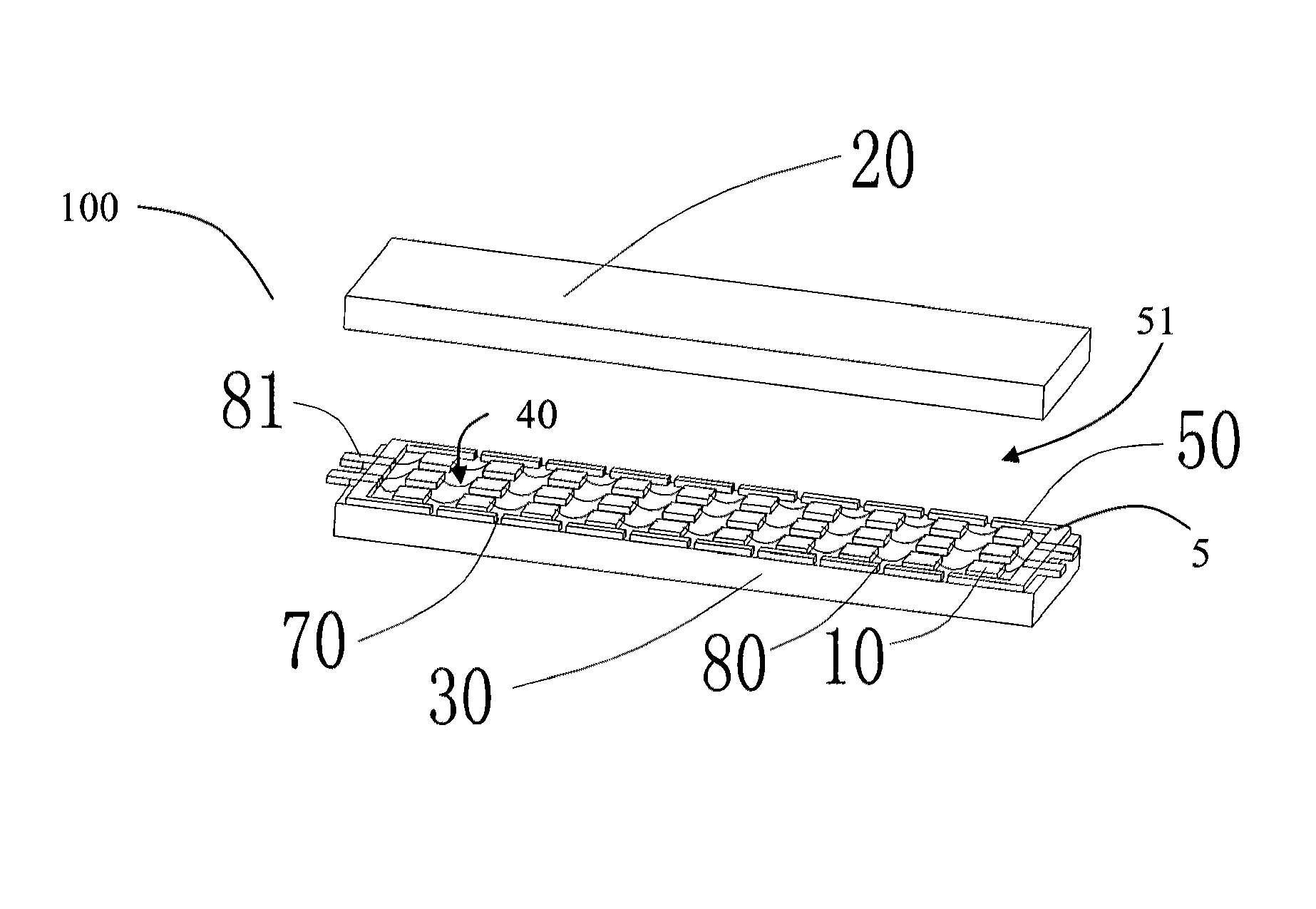
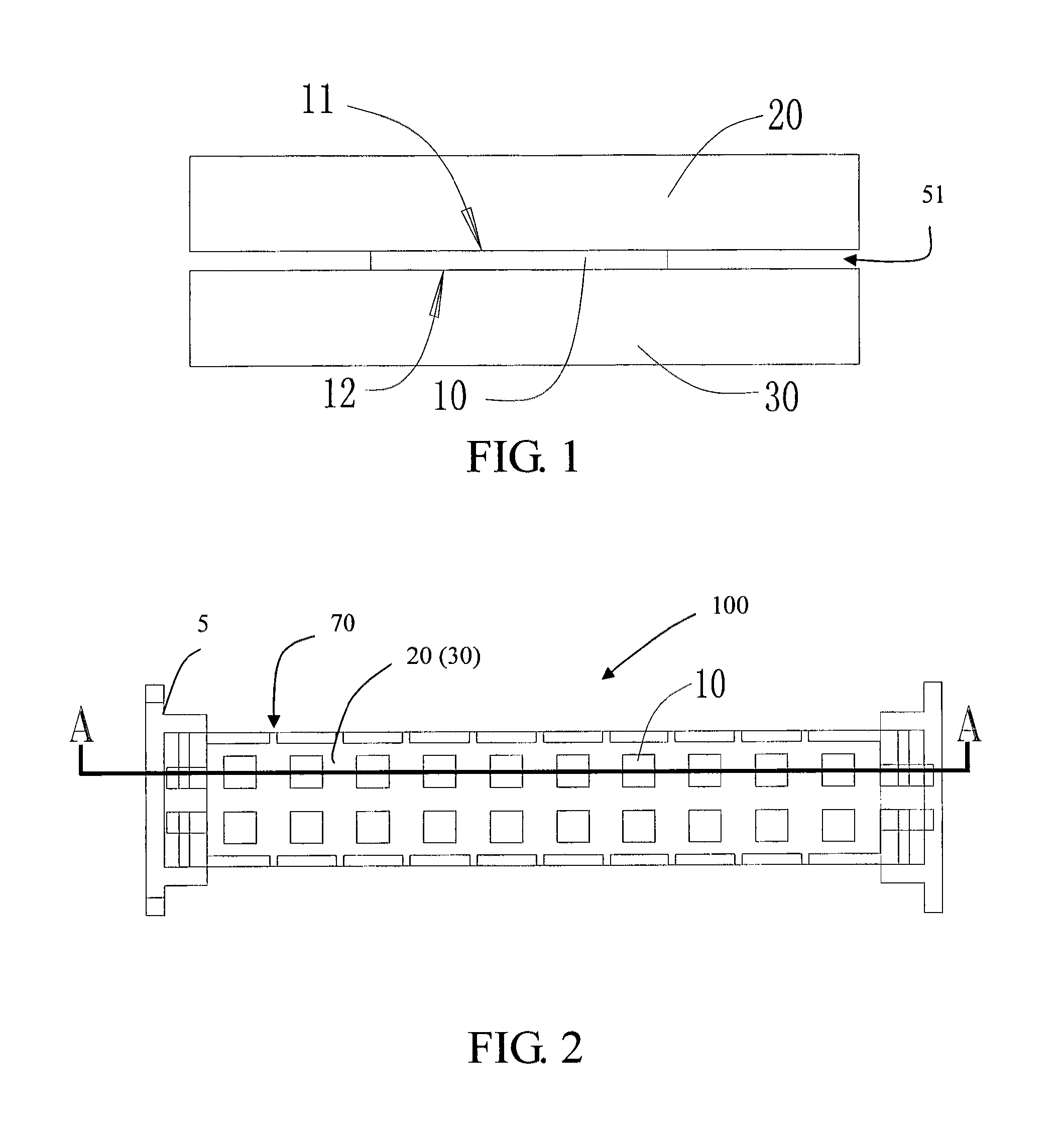
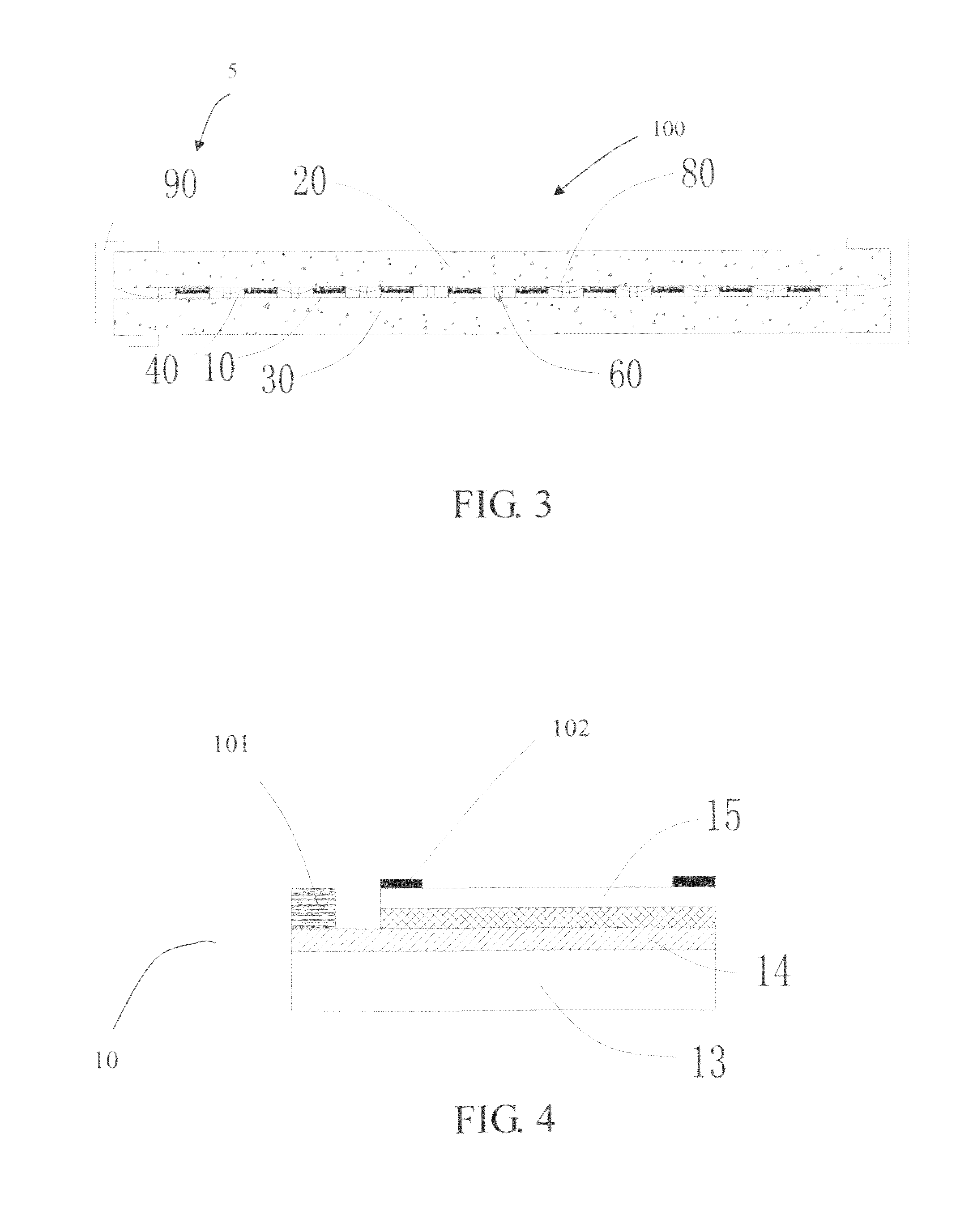
[0082]Referring to FIGS. 1 to 3, 16 and 17 of the drawings, a light-emitting diode (LED) light source according to a preferred embodiment of the present invention is illustrated, wherein the LED light source comprises one or more LED light source arrangements 100 adapted for electrically connecting to a power source and a retention member 5. Each of the LED light source arrangements 100 comprises at least a LED member having first and second light emitting surfaces 11, 12 adapted for electrically connecting to the power source, and first and second fluorescent members 20, 30 provided on the first and second light emitting surfaces 11, 12 respectively, wherein the retention member 5 connects the two fluorescent members 20, 30 in position.

[0083]In particular, referring to FIGS. 2 to 5, the light emitting surfaces 11, 12 of the LED member 10 of each of the LED light source arrangements 100 are adapted for providing illumination through electroluminescence. The LED member 10 is position...


PUM


Abstract

A LED light source includes one or more LED light source arrangements, wherein each of the LED light source arrangements includes a LED member having a first light emitting surface and an opposed second light emitting surface, and two fluorescent members on top of the first and second light emitting surfaces of the LED member respectively to retain the LED member in position such that the illumination generated from the LED member is capable of passing through the two fluorescent members from the two light emitting surfaces respectively. The LED light source arrangement provides illumination at an angle greater than 180° and direct effective heat dissipation at all sides of the LED member.

Description

CROSS REFERENCE OF RELATED APPLICATION[0001]This is a Continuation-In-Part application that claims the benefit of priority under 35 U.S.C.§119 to a non-provisional application, application Ser. No. 13 / 068,162, filed May 3, 2011 now U.S. Pat. No.8,534,866.BACKGROUND OF THE PRESENT INVENTION[0002]1. Field of Invention[0003]The present invention relates to light-emitting diode (LED), and more particularly to a LED light source and manufacture method thereof, wherein the LED light source has a heat dissipation arrangement and is adapted to be embodied in a LED light bulb, providing a high intensity lighting effect, while its manufacturing method is optimized with lowered cost.[0004]2. Description of Related Arts[0005]The conventional LED light source requires effective heat dissipating device for heat dissipation to function effectively. Usually, the heat dissipation mechanism or arrangement involves natural heat convection, addition of cooling fan device, addition of heat pipe, constru...

Claims


Application Information

Patent Timeline
Patent Type & Authority Patents(United States)
IPC IPC(8): F21V9/16
CPCH01L2924/01015F21V29/2225F21K9/135F21Y2101/02F21W2121/00F21V9/16F21K9/50F21V3/00F21Y2111/001F21V29/24F21V29/2293F21Y2105/001H01L2224/45147H01L25/0753H01L2924/00014F21K9/137H01L33/508H01L2224/45144F21V29/77F21V29/83F21V29/85F21K9/232F21K9/233F21K9/60F21Y2115/10F21Y2107/00F21Y2105/16F21Y2103/10F21Y2105/18F21V13/08F21V9/38F21V9/32H01L2924/00H01L2224/48
Inventor CAI, ZOUZOU, JUNMAO, XUEHUA
Owner CAI ZOU
Why Eureka
Try Eureka