Gas-powered device, in particular gas-powered vehicle

A gas-driven and equipment technology, which is applied in the fields of gas-driven vehicles and internal combustion engines, can solve problems such as the economic impact of internal combustion engines, and achieve the effects of reducing manufacturing costs and reducing cold loads.

Inactive Publication Date: 2016-01-27
ROBERT BOSCH GMBH
View PDF5 Cites 3 Cited by
  • Summary
  • Abstract
  • Description
  • Claims
  • Application Information

AI Technical Summary

Problems solved by technology

However, this has a negative impact on the economy of such gas-powered internal combustion engines

Method used


Image

  • Gas-powered device, in particular gas-powered vehicle
  • Gas-powered device, in particular gas-powered vehicle
  • Gas-powered device, in particular gas-powered vehicle

Examples


Embodiment Construction

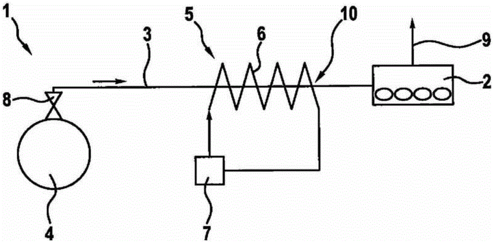
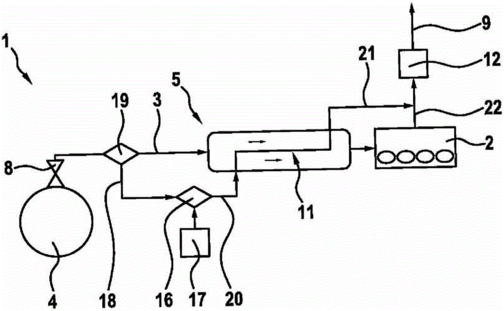
[0026] Refer to the following figure 1 The gas-driven device 1 is described in detail.

[0027] as from figure 1 Obviously, the device 1 comprises an internal combustion engine 2 , an inlet line 3 and a gas tank 4 . In this case, the feed line 3 connects the gas tank 4 to the internal combustion engine 2 . In this case, the feed line 3 includes all components of the fuel supply system from the outlet opening of the gas tank up to the injection injector.

[0028] A tank valve 8 is provided at the outlet of the gas tank 4 in order to throttle the gaseous fuel stored in the gas tank 4 under high pressure.

[0029] Furthermore, the device 1 comprises heating means 5 , which in this embodiment comprise electric heating elements 6 . The electric heating element 6 is connected to an energy supply 7 . The energy supply device 7 is, for example, a battery or a generator or a capacitor, particularly preferably a so-called supercapacitor (electrochemical capacitor). Here, too, a pl...


PUM


Abstract

The present invention relates to a gas powered device comprising an internal combustion engine (2), a gas tank (4) for storage of a gas as fuel for the internal combustion engine, a feed line (3) from the gas tank (4) to the internal combustion engine (2) and a heater (5 ) which heats the gas from the tank (4) discharged gas in the area of the feed line (3).

Description

technical field [0001] The invention relates to a gas-powered appliance, in particular a gas-powered vehicle, which has a gas-driven internal combustion engine. Background technique [0002] For example, in the field of motor vehicles, gaseous fuels such as, for example, natural gas or biogas or the like are increasingly being used in addition to liquid fuels. Here, the gaseous fuel is usually stored under high pressure in gas tanks. Especially at cold ambient temperatures, a temperature-induced increased load on components associated with the gaseous fuel can occur during a cold start of the internal combustion engine. In the case of gases stored at high pressure in gas tanks, this effect is also enhanced by the pressure drop that occurs when flowing into the fuel system due to the Joule-Thomson-Effekt, in which An additional temperature drop of the gaseous fuel occurs in the Sun effect. As a result, in particular components of the fuel system such as, for example, the p...

Claims


Application Information

Patent Timeline
Patent Type & Authority Applications(China)
IPC IPC(8): F02M21/02F02M21/06F02M31/16F02M31/125F01P3/20
CPCF02M21/02F02M21/06F02M31/125F02M31/16Y02T10/12Y02T10/30
Inventor F·米勒A·佩茨A·克劳斯E·奥克伦特M·普罗克施H·寺主
Owner ROBERT BOSCH GMBH
Why Eureka
Try Eureka