Methods and systems for separating condensable vapors from gases

a technology of condensable vapors and gases, applied in the direction of separation processes, machines/engines, lighting and heating apparatus, etc., can solve the problem that the total efficiency of the power plant is significantly reduced by application, and achieve the effect of improving the uniformity of particle sizes and facilitating the continuous operation of the system

Active Publication Date: 2014-05-06
U S BANK TRUST CO NAT ASSOC
View PDF14 Cites 9 Cited by
  • Summary
  • Abstract
  • Description
  • Claims
  • Application Information

AI Technical Summary

Benefits of technology

[0010]The use of a bed of particles in the present invention provides an abundance of surface area for vapor desublimation. The bed of particles improves the efficiency of the system by minimizing the amount of desublimation that occurs on the heat exchanger surface as a total percentage of desublimation vapors. In one embodiment, the bed can be fluidized. In this embodiment, the fluidized particles can impinge the exterior surface of the conduit of the heat exchanger to reduce a buildup of condensed solids, thereby further improving the efficiency of the heat exchanger and allowing for continuous operation of the system.
[0012]The bed of particles can include any type of particulate. In one embodiment, the bed of particles includes particles of the desublimated solid. For example, where carbon dioxide is to be separated from a process stream, the bed of particles can include particles of solid carbon dioxide. The particles can also include other non-condensable materials such as inorganics (silica, oxides, carbonates, etc.) to improve the uniformity of particle sizes in the bed. However, heterogeneous particles are not required.
[0013]During desublimation, the condensation of the vapors on the particles in the bed and / or the conduit causes a buildup of mass in the bed. Solids can be removed from the vessel to maintain a desired bed volume and / or particle size. In one embodiment, particles are removed from a bottom portion of the bed where larger particles tend to accumulate. Removing condensed solids by removing particles from the bed can be used to facilitate continuous operation of the system.

Problems solved by technology

However, its application decreases considerably the total efficiency of the power plant.

Method used


Image

  • Methods and systems for separating condensable vapors from gases
  • Methods and systems for separating condensable vapors from gases
  • Methods and systems for separating condensable vapors from gases

Examples


Embodiment Construction

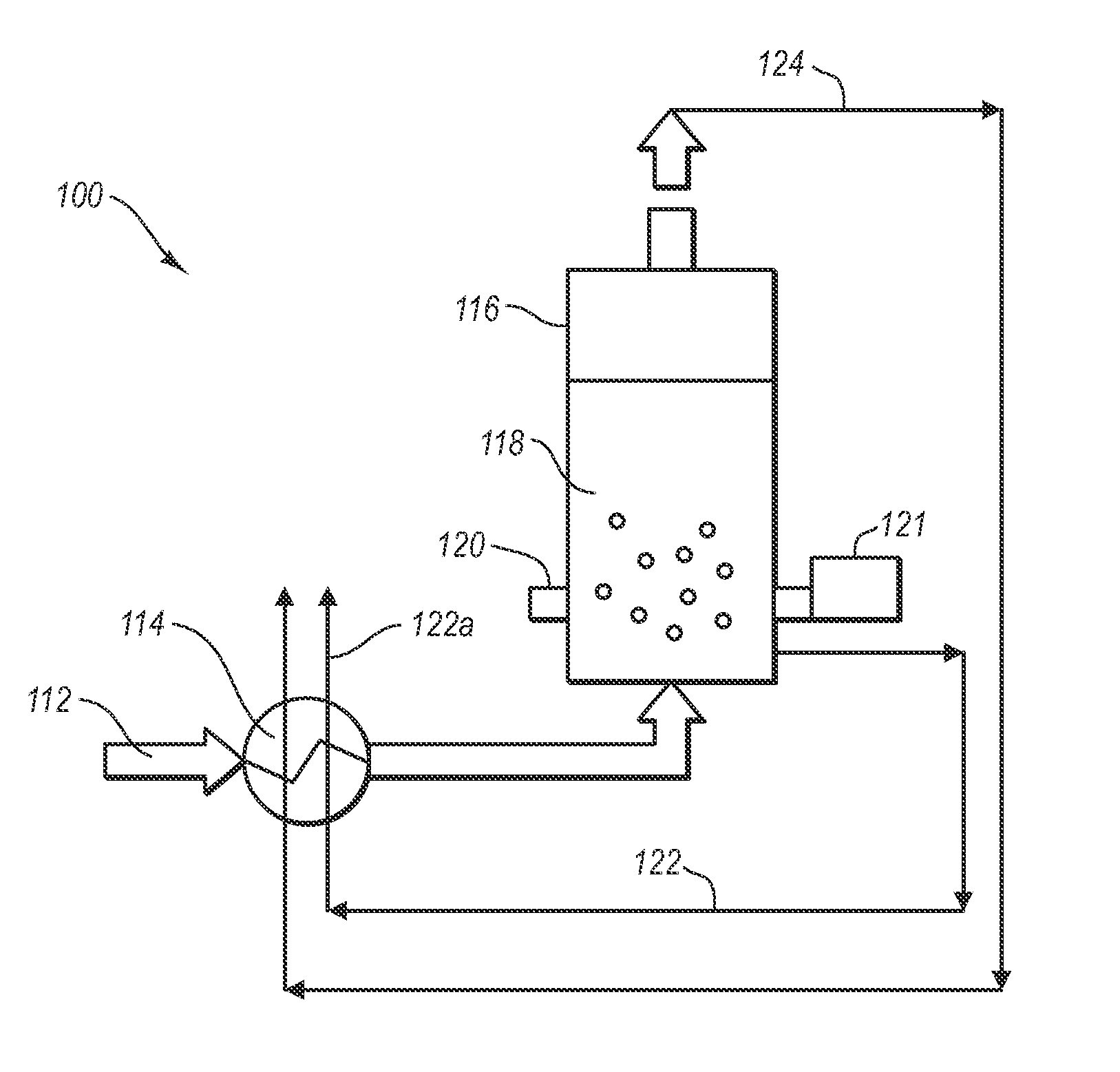
[0030]The systems and methods disclosed herein relate to separating condensable vapors from a process stream (e.g., the flue gas from a power plant) to form a solid and a separated light gas stream. For example, in one embodiment, the methods and systems relate to condensing carbon dioxide vapors from a process stream that includes carbon dioxide and nitrogen. The systems and methods employ a particle bed cooled by an in-bed heat exchanger to desublimate the condensable vapors. The vapors are condensed on the bed particles to form a solid or adsorbed liquid while the lighter gases, which are not condensed, form a separated light-gas stream. The condensed vapors can be used in any desired way. For example, where the condensed vapors are carbon dioxide, the solid carbon dioxide can then be melted and sequestered using any suitable sequestration technique.

[0031]The systems and methods of the invention can be used to separate condensable vapors in any process stream that includes a mixt...


PUM

PropertyMeasurementUnit
pressureaaaaaaaaaa
pressureaaaaaaaaaa
temperatureaaaaaaaaaa

Abstract

Condensable vapors such as carbon dioxide are separated from light gases in a process stream. The systems and methods employ a particle bed cooled by an in-bed heat exchanger to desublimate the condensable vapors from the process stream. The condensable vapors are condensed on the bed particles while the light gases from the process stream, which are not condensed, form a separated light-gas stream. The separated light-gas stream can be used in a recuperative heat exchanger to cool the process stream.

Description

CROSS-REFERENCE TO RELATED APPLICATIONS[0001]This Patent Application is a U.S. National Stage of International Application No. PCT / US2010 / 027518, filed Mar. 16, 2010, which claims the benefit of and priority to U.S. Provisional Patent Application having Ser. No. 61 / 181,655, filed on May 27, 2009 and U.S. Provisional Patent Application having Ser. No. 61 / 210,298, filed on Mar. 16, 2009, the disclosures of which are incorporated herein by reference in their entireties.BACKGROUND[0002]1. The Field of the Invention[0003]The present invention relates to methods and systems for separating desublimating vapors (e.g., carbon dioxide) from gases by desublimating the vapors on a bed of particles.[0004]2. The Related Technology[0005]The separation of carbon dioxide from other light gases such as nitrogen is important for achieving carbon dioxide separation. The flue gases of a conventional power station typically contain from about 4% (by volume) to about 14% carbon dioxide (CO2). CO2 may repr...

Claims


Application Information

Patent Timeline
Patent Type & Authority Patents(United States)
IPC IPC(8): C01B31/22B01D7/02F01N3/00B01D53/02B01D53/00C01B32/55
CPCF23J2900/15061B01D2257/504Y02C10/08B01D7/02F23J2219/70C01B31/22B01D2257/80B01D2257/302Y02C10/04B01D2257/404B01D53/002F25J1/0027F01N3/005Y02T10/20C01B32/55F25J3/067F25J2205/20F25J2205/24F25J2210/70F25J2220/82F25J2230/30F25J2235/80F25J2270/02F25J2270/04Y02P20/129Y02C20/40Y02P20/151Y02P70/10Y02T10/12F25J2205/30
Inventor BAXTER, LARRY, L.
Owner U S BANK TRUST CO NAT ASSOC
Why Eureka
Try Eureka