
Method for panel reliability testing and device thereof

a technology for liquid crystal display and reliability testing, applied in the direction of electrical testing, measurement devices, instruments, etc., can solve the problem of increasing manufacturing costs and achieve the effect of solving low testing efficiency and high testing costs

Active Publication Date: 2014-05-06
TCL CHINA STAR OPTOELECTRONICS TECH CO LTD
View PDF18 Cites 0 Cited by
  • Summary
  • Abstract
  • Description
  • Claims
  • Application Information

AI Technical Summary

Benefits of technology

The present invention provides a method and device for testing LCD panels, which solves the issues of high testing costs and low efficiency. This method involves aging testing, which reduces the manufacturing time of LCD panels and increases production efficiency.

Problems solved by technology

At present, the reliability testing is performed on an assembled LCD panel, which not only wastes time but also needs to prepare for many components, such as a driver circuit and a backlight module, for the LCD panel undergoing the reliability testing.
Accordingly, manufacturing cost is increased.
However, a prior device for the LCD panel reliability is seldom put into a chamber of a testing equipment because such the prior device is bulky and expensive.

Method used


Image

  • Method for panel reliability testing and device thereof
  • Method for panel reliability testing and device thereof
  • Method for panel reliability testing and device thereof

Examples


Embodiment Construction

[0032]Spatially relative terms, such as “beneath”, “below”, “lower”, “above”, “upper” and the like, may be used herein for ease of description to describe one element or feature's relationship to another element(s) or feature(s) as illustrated in the figures. It will be understood that the spatially relative terms are intended to encompass different orientations of the device in use or operation in addition to the orientation depicted in the figures.

[0033]In the following description, units with a similar structure will be labeled by the same reference numerals though they are shown in different drawings.

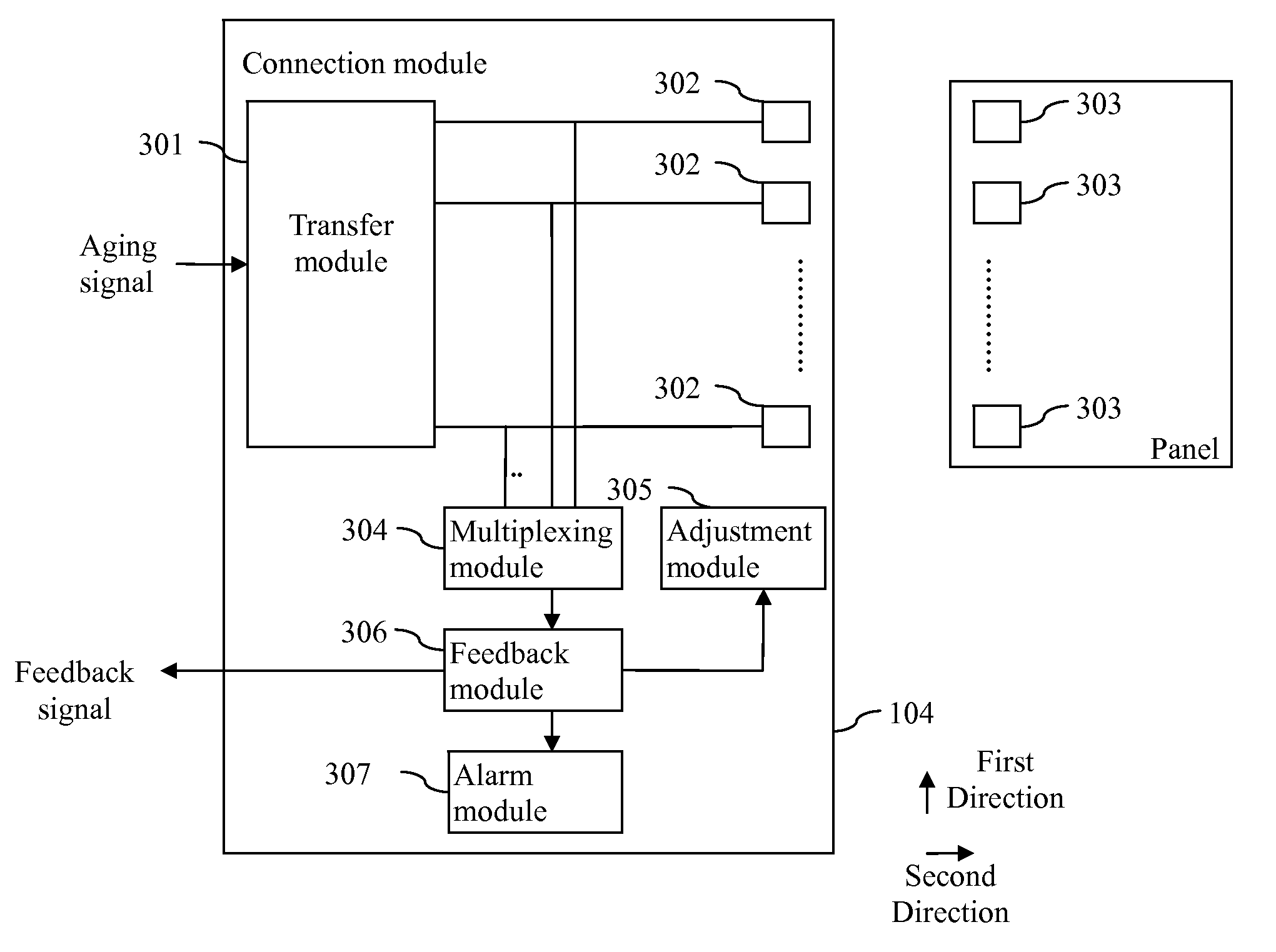
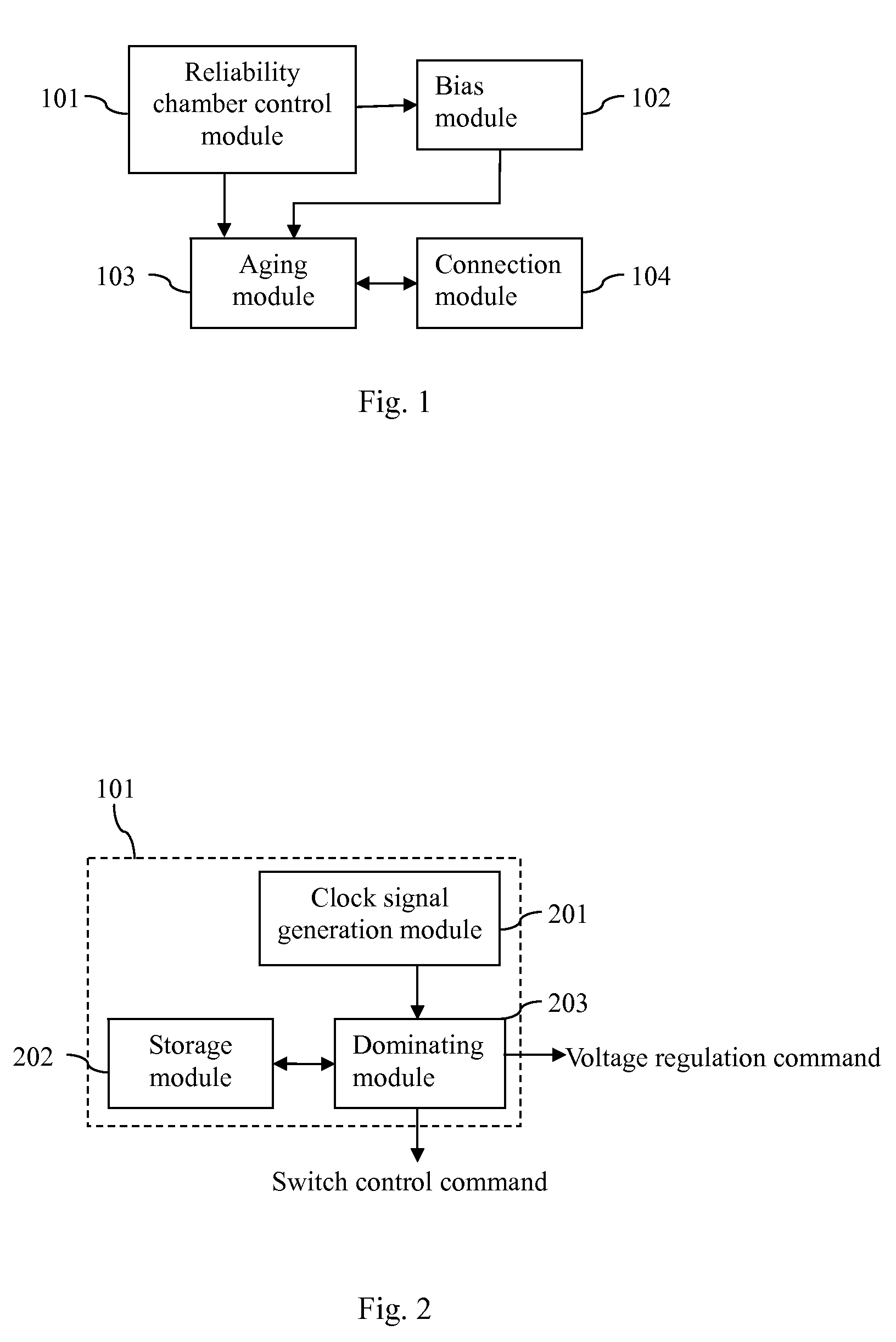
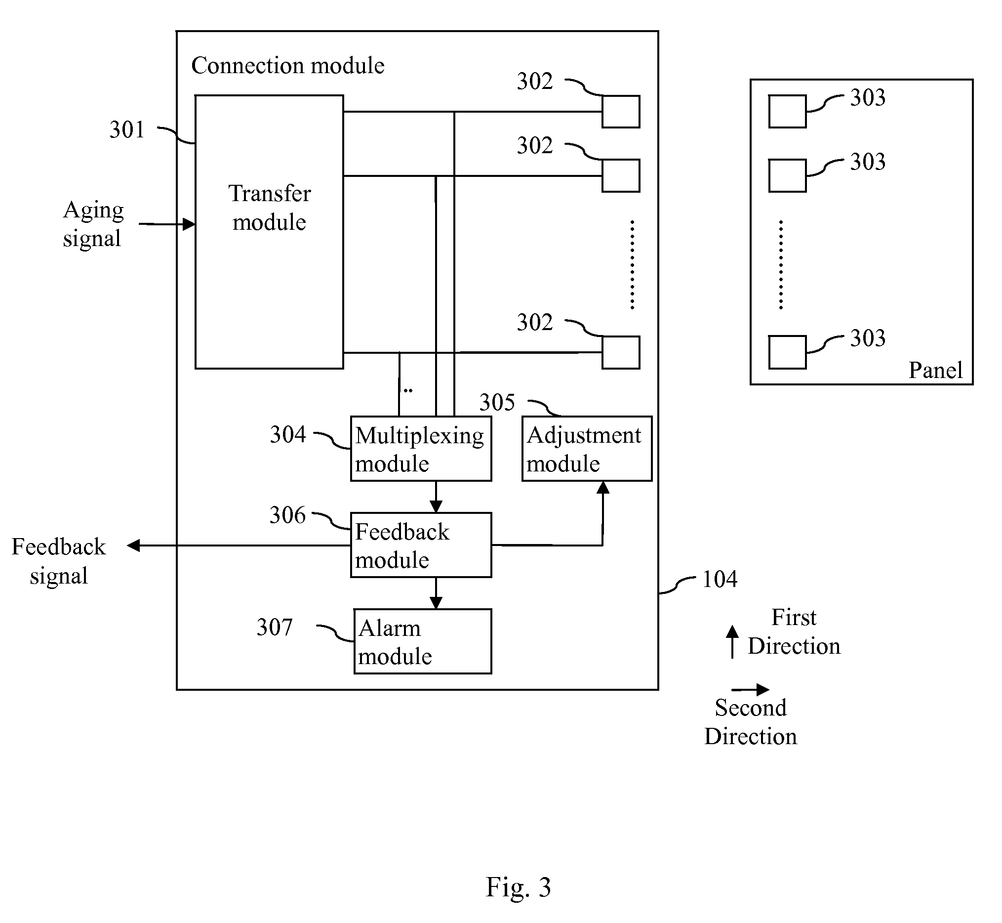
[0034]Referring to FIG. 1, a device for panel reliability testing comprises a reliability chamber control module 101, a bias module 102, an aging module 103, and a connection module 104. As shown in FIG. 2, the reliability chamber control module 101 comprises a dominating module 203, a storage module 202, and a clock signal generation module 201. The storage module 202 stores progra...


PUM


Abstract

A device for panel reliability testing and method thereof are proposed. The device includes a connection module, for connecting the panel and an aging module; a reliability chamber control module for sending a voltage regulation command to a bias module and / or a switch control command to the aging module; the bias module, for regulating voltage and transmitting information about voltage regulation to the aging module; and the aging module, for performing an aging operation on the panel depending on the switch control command sent from the reliability chamber control module and the information about voltage regulation transmitted from the bias module. Compared with the prior art, LCD panels undergo the aging testing before being packaged, thereby shortening a time period of manufacturing LCD panels and enhancing production efficiency.

Description

BACKGROUND OF THE INVENTION[0001]1. Field of the Invention[0002]The present invention relates to a device for testing a liquid crystal display (LCD) panel, and more particularly, to a device for panel reliability testing.[0003]The present invention further relates to a method for testing a liquid crystal display panel, and more particularly, to a method for panel reliability testing.[0004]2. Description of the Prior Art[0005]Generally speaking, each liquid crystal display panel needs to undergo reliability testing. Reliability is defined as the probability that a functional unit will perform its required property or function under stated environments / conditions for a specific period of time. For the reliability testing, aging testing is one of the important testing items.[0006]At present, the reliability testing is performed on an assembled LCD panel, which not only wastes time but also needs to prepare for many components, such as a driver circuit and a backlight module, for the LC...

Claims


Application Information

Patent Timeline
Patent Type & Authority Patents(United States)
IPC IPC(8): G01R31/00G01R31/26
CPCG09G3/006G09G3/3611
Inventor LIAO, SHIUE-SHIHTSAI, JUNG-MAOZHANG, XIAO-XIN
Owner TCL CHINA STAR OPTOELECTRONICS TECH CO LTD
Learn More