
Fan rotation speed test device

a technology of rotation speed and test device, which is applied in the direction of mechanical equipment, machines/engines, instruments, etc., can solve the problems of low test efficiency of test device, slow communication between test device and computer, and complicated structure of the test device used in the laboratory for testing the rotation speed of the fan

Inactive Publication Date: 2013-01-03
HONG FU JIN PRECISION IND (SHENZHEN) CO LTD +1
View PDF5 Cites 2 Cited by
  • Summary
  • Abstract
  • Description
  • Claims
  • Application Information

AI Technical Summary

Benefits of technology

The patent text describes a problem with a fan test device in a laboratory. The device has a complicated structure and requires an additional communication interface to connect it to a computer, which results in slow communication and low test efficiency. The technical effect of this problem is to slow down the process of testing fan speed in the laboratory.

Problems solved by technology

One test device used in a laboratory for testing rotation speed of fans has a very complicated structure.
As a result of the additional interface, the communication between the test device and the computer is slow, and test efficiency of the test device is very low.

Method used


Image

  • Fan rotation speed test device
  • Fan rotation speed test device
  • Fan rotation speed test device

Examples


Embodiment Construction

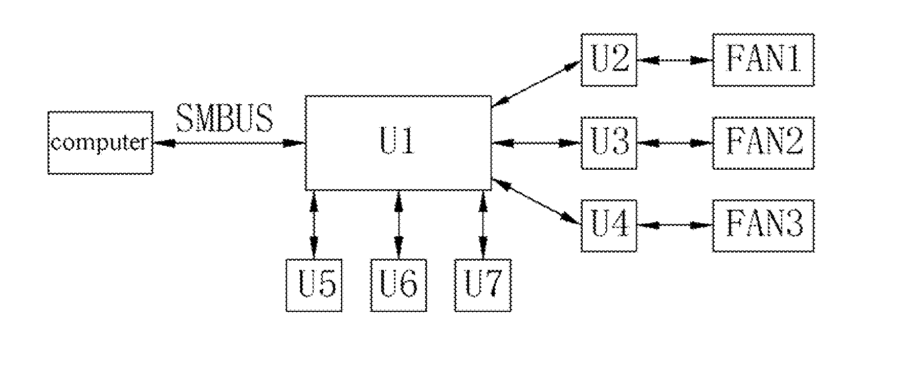
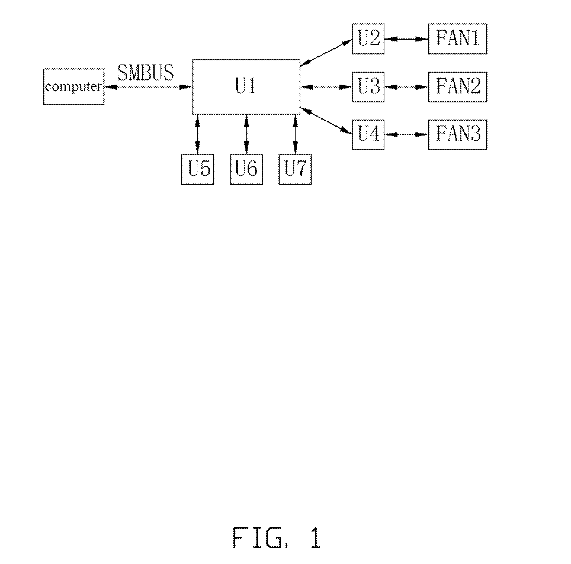
[0009]Referring to FIG. 1, a fan rotation speed test device according to an exemplary embodiment of the disclosure includes an information processing chip U1, three signal amplifying units U2-U4, and three indicating units U5-U7. The fan test device can test rotation speed of three fans FAN1-FAN3 simultaneously.

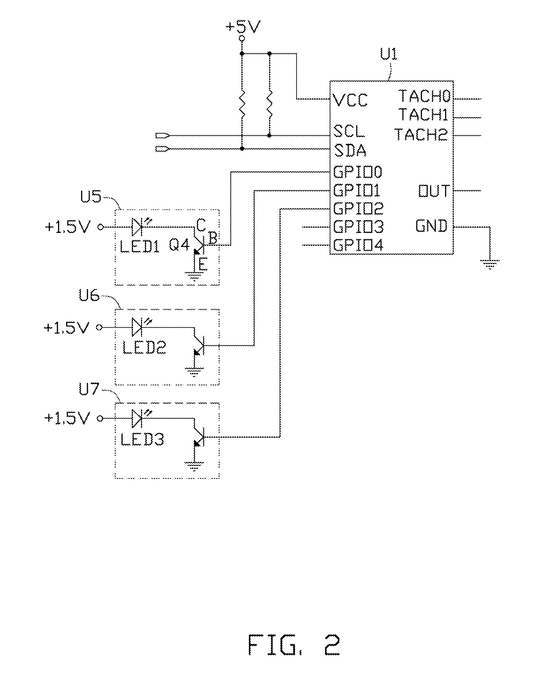
[0010]Also referring to FIGS. 2-3, the chip U1 is a MAX6651. Pins SCL and SDA of the chip U1 connect to an interface SMBUS (System Management Bus). The interface SMBUS is compatible with a memory socket on a mainboard of a computer. When the fan test device is connected to the computer via the interface SMBUS, communication between the fan device and the computer is established. The pins SCL and SDA and a pin VCC of the information processing chip U1 connect to a 5-volt direct current power source. A pin GND of the information processing chip U1 connects to ground.

[0011]Each fan has four pins 1-4. The pins 1 of the fans FAN1-FAN3 connect to the signal amplifying units U2-U4 r...


PUM


Abstract

A fan rotation speed test device connected to a computer includes an information processing chip, an indicating unit, and an interface. The interface is compatible with a memory socket on a mainboard of the computer. The computer transfers control instructions to the information processing chip via the interface. After receiving the control instructions, the information processing chip outputs PWM signals by executing programs therein to modulate the rotation speed of a fan. The information processing chip collects rotation speed signals of the fan, then judges if the rotation speed of the fan is according to a predetermined standard by executing arithmetic programs. The information processing chip outputs test result signals to the indicating unit for display.

Description

BACKGROUND[0001]1. Technical Field[0002]The present disclosure relates to test devices, and particularly to a test device which has an interface compatible with a computer and can test rotation speed of a fan.[0003]2. Description of Related Art[0004]One test device used in a laboratory for testing rotation speed of fans has a very complicated structure. An additional communication interface is needed to connect the test device with a computer. As a result of the additional interface, the communication between the test device and the computer is slow, and test efficiency of the test device is very low.[0005]What is needed, therefore, is a fan rotation speed test device which can overcome the limitations described.BRIEF DESCRIPTION OF THE DRAWINGS[0006]FIG. 1 is a constitution block diagram of a fan rotation speed test device in accordance with an exemplary embodiment of the disclosure.[0007]FIG. 2 shows a part of a circuit of the fan rotation speed test device of FIG. 1.[0008]FIG. 3 ...

Claims


Application Information

Patent Timeline
IPC IPC(8): G01P3/00G06F15/00
CPCF04D27/001G01P21/02F04D27/004Y02B30/70
Inventor SONG, YONG-JUNHUANG, YONG-ZHAO
Owner HONG FU JIN PRECISION IND (SHENZHEN) CO LTD
Learn More