Tag communication device and tag communication method

a communication device and tag technology, applied in the field of tag communication devices and tag communication methods, can solve the problems of enlargement of the system, high possibility of non-communication, wasting power to have the reader/writer transmit the interrogating wave, etc., to prevent the occurrence of tag confusion, improve communication between tags, and reduce power consumption

Active Publication Date: 2010-08-26
ORMON CORP
View PDF6 Cites 22 Cited by
  • Summary
  • Abstract
  • Description
  • Claims
  • Application Information

AI Technical Summary

Benefits of technology

[0041]As described above, according to the present invention, a mobile object is detected using Doppler measurement, and an interrogating wave is transmitted only when the mobile object is detected. Thus, power consumption is reduced, an occurrence of tag confusion is prevented, and communication between tags is improved.

Problems solved by technology

However, in such an RFID system, the reader / writer detects presence of the tag with only the transmission of the interrogating wave.
It is a waste of power to have the reader / writer transmit the interrogating wave on a steady basis.
If a plurality of reader / writers is installed and the number of channels assigned to each reader / writer is few, radio interference may occur between the reader / writers or tag confusion may occur in the communication with the tag when each reader / writer transmits the interrogating wave, whereby a possibility of non-communication becomes high.
However, the system that detects the mobile object using the sensor and communicates with the tag leads to enlargement of the system and also results in high cost.
In addition, the occupying band of the frequency becomes wide when the transmission speed becomes high, which may become the cause of interference between channels.

Method used


Image

  • Tag communication device and tag communication method
  • Tag communication device and tag communication method
  • Tag communication device and tag communication method

Examples


first embodiment

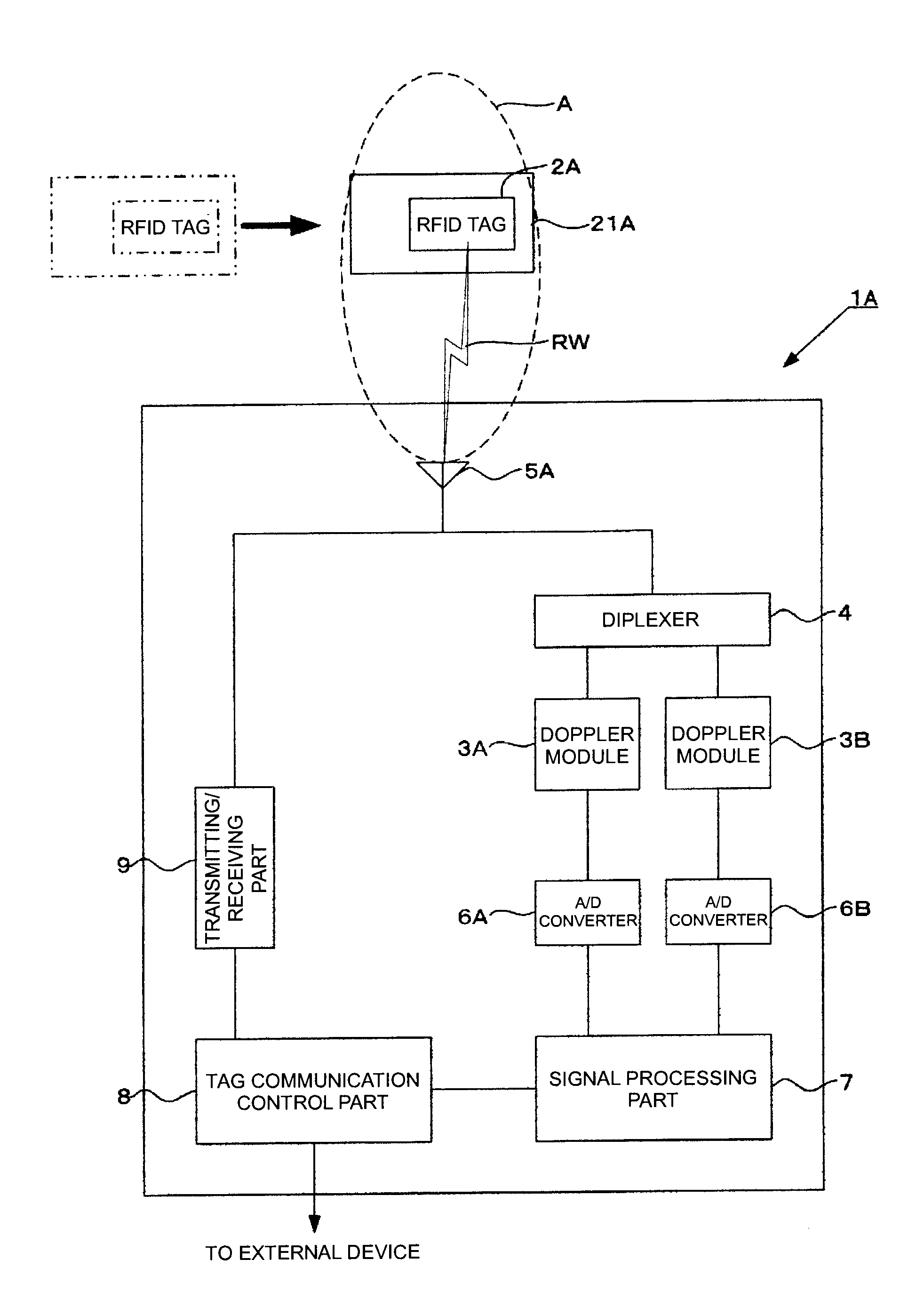
[0082]In a reader / writer 1A according to the first embodiment, the stop tag detection process and the tagless movement detection process are also performed, other than performing the process (hereinafter referred to as “basic process of the present invention”) in which the reader / writer 1A transmits the interrogating wave RW only when the RFID tag 2A is detected by the tag movement detection process, as described below.

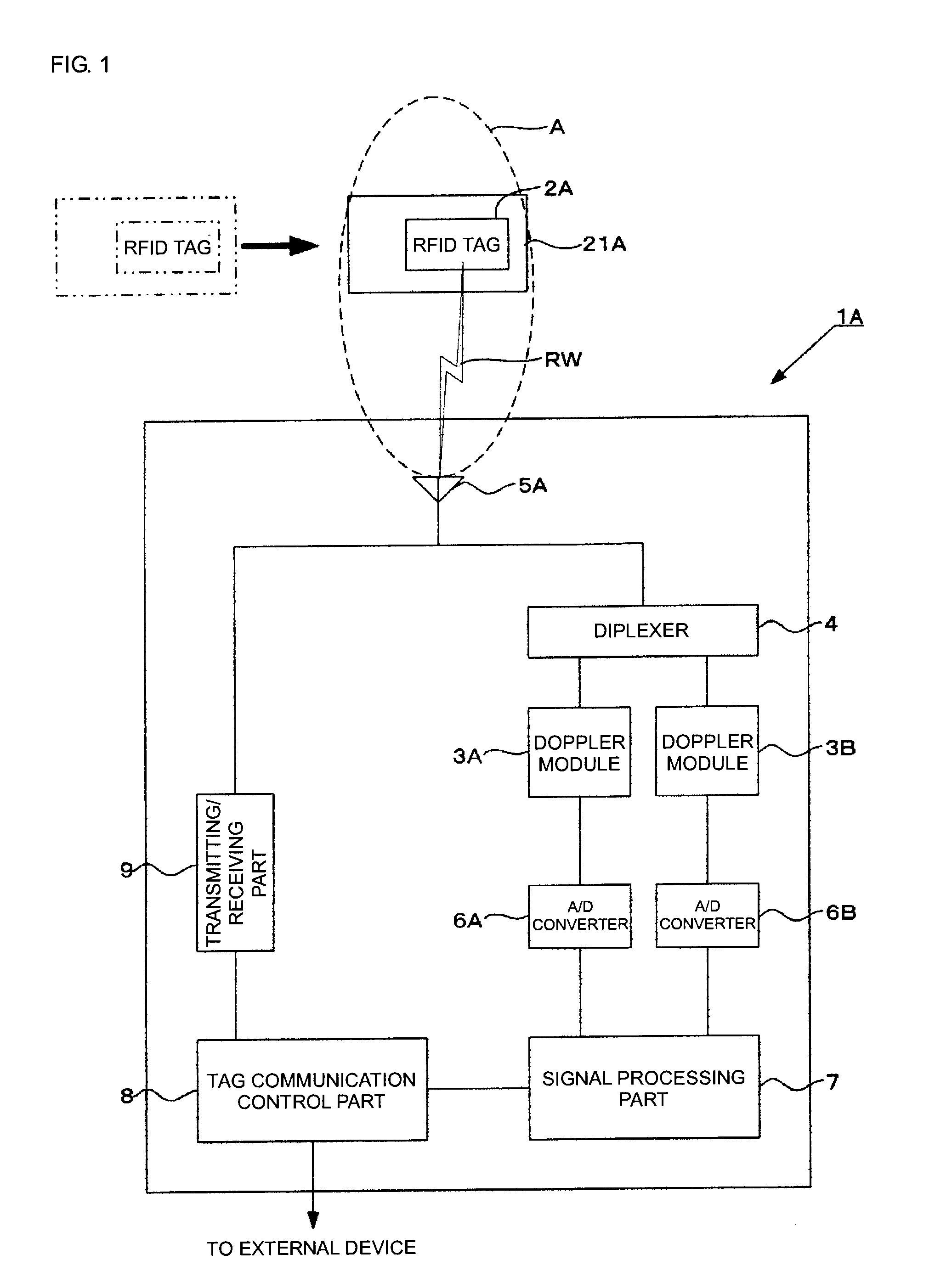
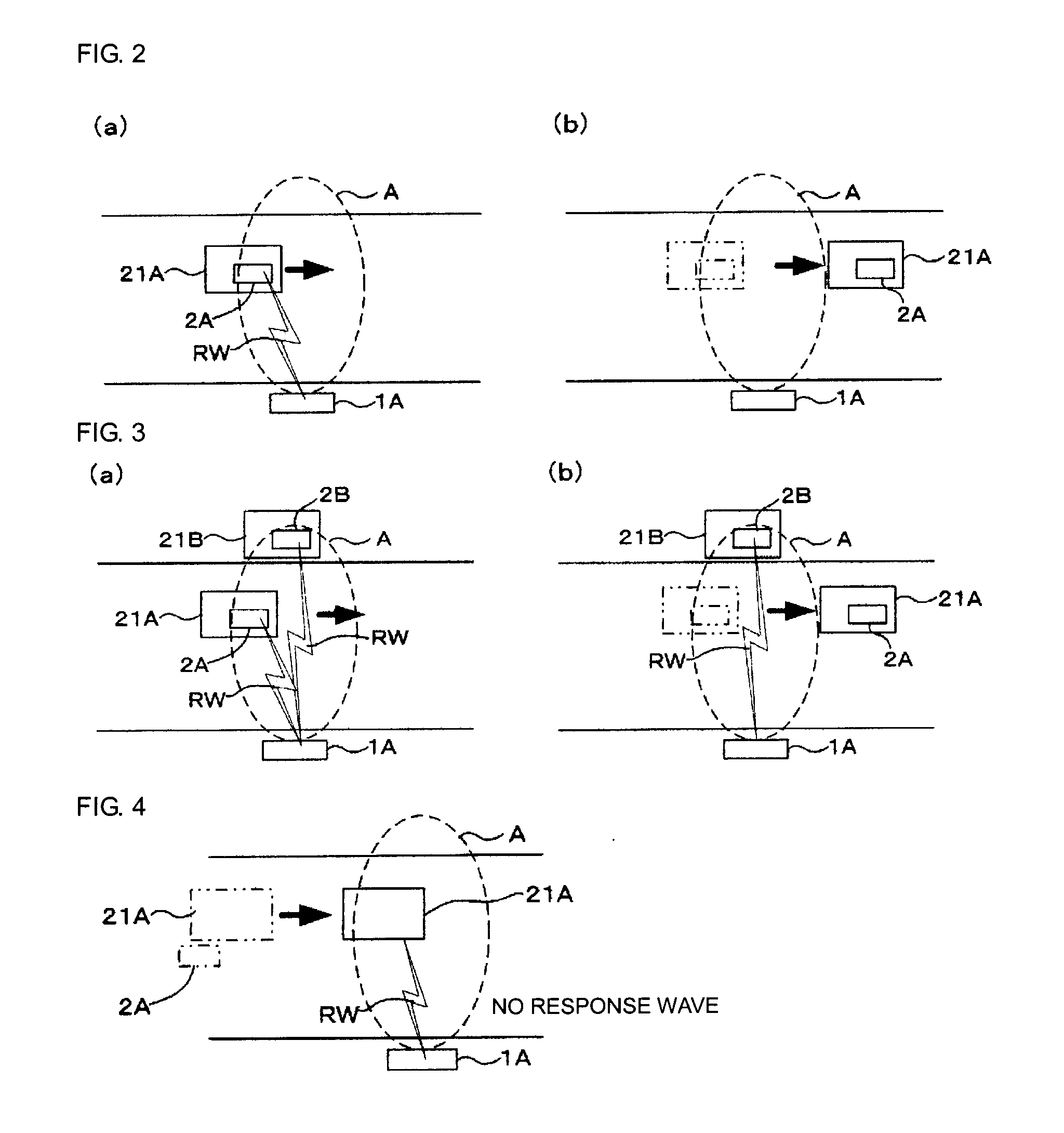
[0083]FIGS. 2(a) and 2(b) are schematic views describing a basic process of the present invention, FIGS. 3(a) and 3(b) are schematic views describing the stop tag detection process, FIG. 4 is a schematic view describing the tagless movement detection process, and FIG. 5 is a flowchart showing the basic process, the stop tag detection process and the tagless movement detection process.

[0084]As shown in FIG. 5, when the reader / writer 1A is activated, the mobile object detection process is first performed (S100). The mobile object detection process is as described above,...

second embodiment

[0093]In a reader / writer 1A according to the second embodiment, in addition to the basic process described above, a transmission power adjustment process for setting the transmission power high or low according to the distance with the RFID tag 2A when transmitting the interrogating wave RW is performed.

[0094]FIGS. 6(a) and 6(b), and FIGS. 7(a) and 7(b) are schematic views describing the transmission power adjustment process, and FIG. 8 is a flowchart showing the transmission power adjustment process.

[0095]As shown in FIG. 8, when the reader / writer 1A is activated, the mobile object detection process is performed until the cargo 21A is detected (S200, S201). This process is a process similar to S100, S101, and thus the description thereof will not be given. If the cargo 21A is detected (Y in S201) as a result of the mobile object detection process, the distance between the reader / writer 1A and the cargo 21A is measured (S202). Assuming the transmission wave with the first frequency ...

third embodiment

[0101]In a reader / writer 1A according to the third embodiment, a communication missing detection process, that is, a process of detecting a state where communication failure occurred between the reader / writer 1A and the RFID tag 2A attached to the cargo 21A, and notifying a communication error to the external device and the like is performed in addition to the basic process of the present invention described above. FIG. 9 is a flowchart showing the communication missing detection process.

[0102]As shown in FIG. 9, when the reader / writer 1A is activated, a reception flag is first set to OFF (S300), and thereafter, the mobile object detection process (S301, S302) is performed until the cargo 21A is detected. This process is the process similar to S100, S101, and thus the description thereof will not be given. If the cargo 21A is detected (Y in S302) as a result of the mobile object detection process, the inter-tag communication process is performed (S303), and whether or not the respon...


PUM


Abstract

To improve communication between tags by causing a mobile object having a RFID tag attached to transmit an interrogating wave only when moving in a communication range to reduce power consumption and prevent occurrence of tag confusion. By acquiring two Doppler signals from 2-frequency transmission waves (CW) with different frequencies and respective reflected waves and detecting phase difference from the Doppler signals, a cargo (21A) is detected to be moving in the communication range (A). Only when the movement is detected, a reader-writer (1A) transmits the interrogating wave (RW).

Description

TECHNICAL FIELD[0001]The present invention relates to tag communication devices and tag communication methods, and in particular, to a tag communication device and a tag communication method suited for reducing power consumption when wirelessly communicating with a mobile object with an RFID (Radio Frequency Identification) tag attached, and for preventing an occurrence of tag confusion.BACKGROUND ART[0002]In the field of physical distribution, an RFID system of attaching an RFID tag (hereinafter simply referred to as “tag”) to a mobile object such as a cargo and performing wireless communication between the tag and a tag communication device such as a reader / writer is recently adopted, so that cargo management is carried out by such an RFID system. According to the RFID system, the reader / writer is installed along conveying means such as a belt conveyor, and an interrogating wave is transmitted from the reader / writer. A response wave is then transmitted from the tag attached to the...

Claims


Application Information

Patent Timeline
Patent Type & Authority Applications(United States)
IPC IPC(8): G06K7/01
CPCG01S13/38G01S13/50G01S13/751G06K7/10435G01S13/878G06K7/0008G01S13/825
Inventor KASAI, HIROKAZUKAWAI, TAKEHIRO
Owner ORMON CORP
Why Eureka
Try Eureka