Chip testing device and chip testing system for testing memory chips
a testing device and memory chip technology, applied in the direction of electronic circuit testing, measurement devices, instruments, etc., can solve the problems of low testing efficiency and easy damage to the contact of the memory chip, and achieve the effect of improving the problem, low testing efficiency and easy damag
- Summary
- Abstract
- Description
- Claims
- Application Information
AI Technical Summary
Benefits of technology
Problems solved by technology
Method used
Image
Examples
first embodiment
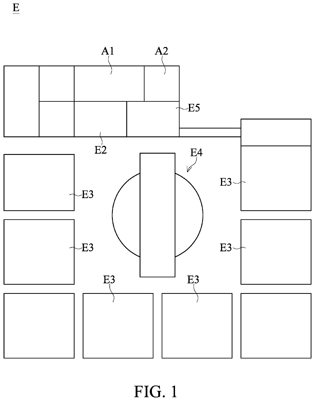
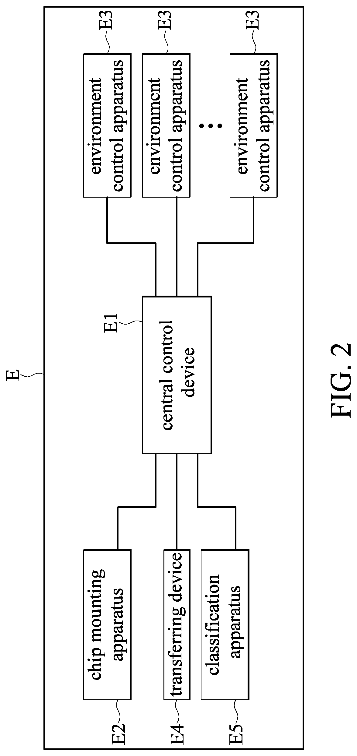
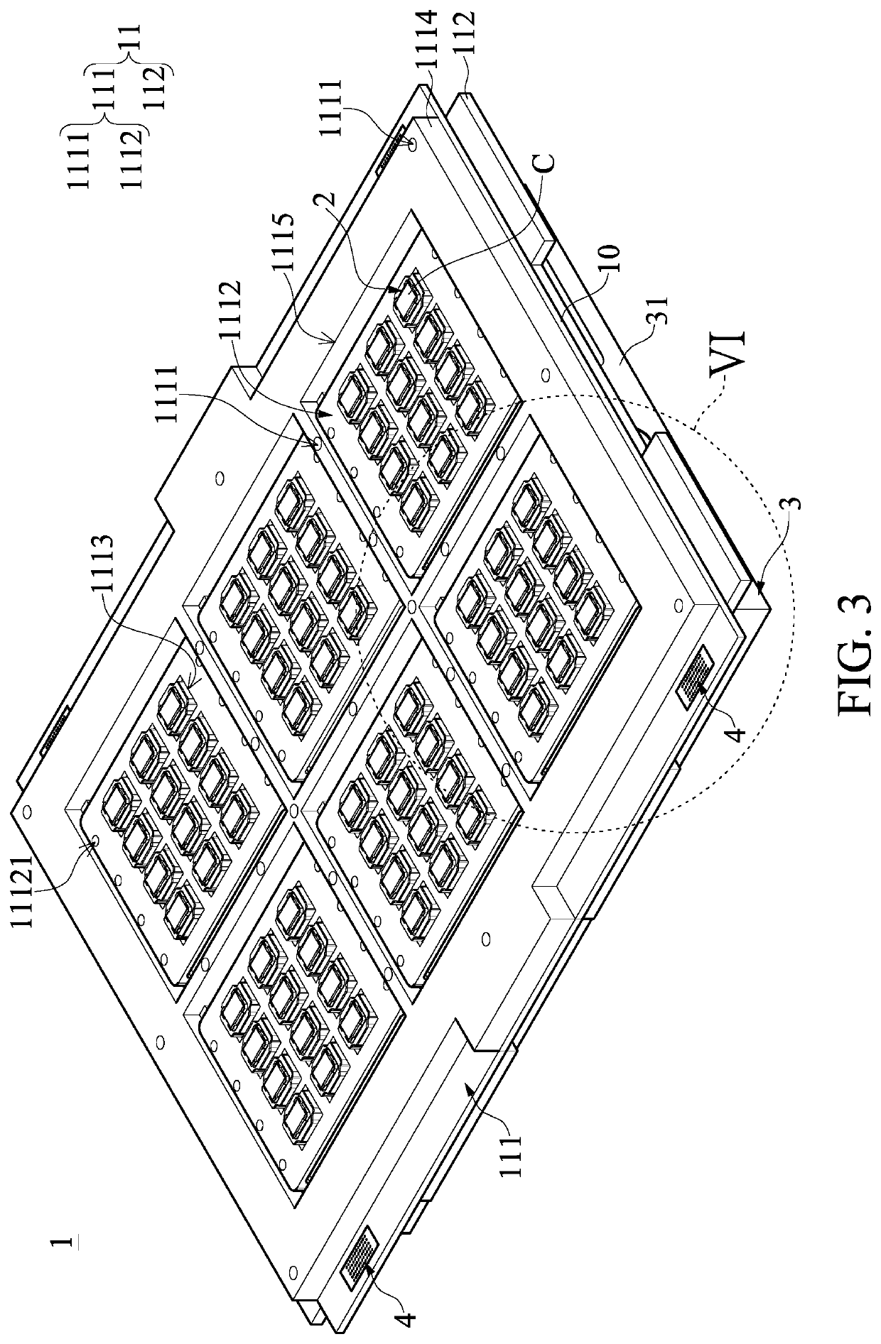
[0109]Referring to FIG. 24, FIG. 24 is a flow chart showing a chip testing method that is implemented by using the chip testing system according to the present disclosure. The chip testing system E can perform the predetermined testing process on the chips C by implementing the following chip testing method. The chip testing method includes: a chip mounting step S1 implemented by using the chip mounting apparatus E2 to respectively dispose a plurality of chips C from a tray onto the electrical connection sockets 2 of the chip testing device 1; a moving-in step S2 implemented by transferring the chip testing device 1 carrying the chips C into one of the accommodating chambers E311 of one of the environment control apparatuses E3; a temperature adjusting step S3 implemented by controlling an operation of the temperature adjusting device E34 in the one of the accommodating chambers E311 so that the chips C are in an environment having a predetermined temperature; a testing step S4 impl...
third embodiment
[0113]Referring to FIG. 26, FIG. 26 is a flow chart showing a chip testing method that is implemented by using the chip testing system according to the present disclosure. The chip testing method in the present embodiment further includes a separating step S5 that is between the testing step S4 and the moving-out step S6 and is not disclosed in the above embodiments. Moreover, the separating step S5 is implemented by separating the power supply member 4 of the chip testing device 1 from the chamber terminals E33 of the one of the accommodating chambers E311 after the predetermined testing process for the chips C connected to the chip testing device 1 is finished.
[0114]As shown in FIG. 3, FIG. 17, and FIG. 18, the environment control apparatus E3 further includes a plurality of lift devices E38, and each of the accommodating chambers E311 is provided with one of the lift devices E38 therein. Each of the lift devices E38 is connected to the environment status control devices of the ce...
fourth embodiment
[0125]Referring to FIG. 27, FIG. 27 is a flow chart showing a chip testing method that is implemented by using the chip testing system according to the present disclosure. The chip testing system E of the present embodiment is configured to test a plurality of memory chips (i.e., the chips C) by implementing the chip testing method. The difference between the chip testing method in the present embodiment and other embodiments of the present disclosure is described as follows. In the present embodiment, the temperature adjusting step S3 and the testing step S4 can be repeatedly implemented for two times after the moving-in step S2 and before the moving-out step S5, and includes a temperature adjusting step S31, a testing step S41, a temperature adjusting step S32, and a testing step S42.
[0126]In the temperature adjusting step S31 and the testing step S41 (i.e., the temperature adjusting step S3 and the testing step S4 are implemented for a first time of the two times), the temperatur...
PUM
 Abstract
Description
Claims
Application Information
 - R&D
- Intellectual Property
- Life Sciences
- Materials
- Tech Scout
- Unparalleled Data Quality
- Higher Quality Content
- 60% Fewer Hallucinations
Browse by: Latest US Patents, China's latest patents, Technical Efficacy Thesaurus, Application Domain, Technology Topic, Popular Technical Reports.
© 2025 PatSnap. All rights reserved.Legal|Privacy policy|Modern Slavery Act Transparency Statement|Sitemap|About US| Contact US: help@patsnap.com


