Multi-angle ultra wideband antenna with surface mount technology

a surface mount and antenna technology, applied in the direction of antennas, antenna supports/mountings, radiating elements structural forms, etc., can solve the problems of reducing the antenna at low frequencies and increasing the integration complexity of the antenna, so as to simplify the assembling process of the antenna integration, the overall structural rigidity is high, and the antenna is easy to be removed

Inactive Publication Date: 2014-05-06
TAOGLAS GROUP HLDG LTD
View PDF4 Cites 5 Cited by
  • Summary
  • Abstract
  • Description
  • Claims
  • Application Information

AI Technical Summary

Benefits of technology

[0009]It is another object of the present invention to provide an antenna with sufficient gain, efficiency, bandwidth and omni-directional properties to be used in other frequencies such as 2400 and 2500 MHz used in WiFi, WiMAX, ISM, ZigBee and emerging technologies in the frequencies from 1000 MHz to 1400 MHz and from 2700 MHz to 3100 MHz.
[0012]The present invention achieves the above and other objects by providing a flexible antenna for electronic devices, that can simplify the assembling process in the antenna integration, incorporating the surface mount device technology in the antenna structure to a printed circuit board on said second substrate of the antenna onto said printed circuit board, having a plurality of first solder for physical attachment and a second solder pad electrically connected onto said printed circuit board for the radio signal propagation. The flexible material is not deformed by the high temperatures in the surface mount process and / or not suffering any kind of shrinking effect in the substrate.
[0013]A stiffer has been incorporated to assist a successful surface mounting assembly procedure of the antenna to the device, it can be made by any Flame Retardant 4 (FR-4) material or the UL-94-V0 standard polyimide attaching it to the antenna with a very fine glue. This glue can afford the high temperature for the SMD process. This stiffer can be easily removed after the surface mount process when is concluded without leave any residue. Due the light in weight of the antenna could not be accurate to stay on its placed location on the device and / or too thin in thickness to maintain its proper structural shape during the entire procedure as consequence from violent pick-and-place movements for all components of the device-board. Usefulness of such as stiffer is to provide overall structural rigidity and add weight to the flexible antenna to maintain the placement in the SMD production, having an extra in weight pressing down the antenna and having a better contact, avoiding inaccurate soldering.
[0014]In summary, the low profile flexible antenna in accordance with the present invention based essentially on the proven flexible circuit technology is particularly useful in mobile applications such as for consumer electronic devices, having a unique characteristic where in one structure high performance, surface mountable and having different bending angles to conform different shapes are achieved, ending in easy, practical, cheap and time saving at the integration. Automated integration becomes possible avoiding labors such as soldering and installation of pogo pin and spring contacts, resulting in a reliable and consistence antenna performance and the present invention can be delivered on tapes and reels just like SMD diodes, resistors and others.

Problems solved by technology

With the introduction of the new 700 MHz (LTE) band in North America, it is indeed higher complexity for its integration while keeping the antenna size similar to quad-band antenna, satisfying the current demands for small devices.
Over the years is observed how the devices tend to be smaller, but with the new low frequency band presents a real challenge in miniaturization and the bandwidth must be increased to incorporate more new frequencies: 1710 and 2100 MHz bands.
Reducing the antenna at low frequencies present a real challenge, but some techniques are studied like increasing the dielectric constant of the material that enclose the antenna, bending the metallic radiated element and find the specific geometrical shape that reduce the space occupied by the antenna.

Method used


Image

  • Multi-angle ultra wideband antenna with surface mount technology
  • Multi-angle ultra wideband antenna with surface mount technology
  • Multi-angle ultra wideband antenna with surface mount technology

Examples


Embodiment Construction

[0026]The present invention is described in more detail with reference to the accompanying drawings, which should not be construed as limiting the embodying of the antenna of the present invention set forth therein.

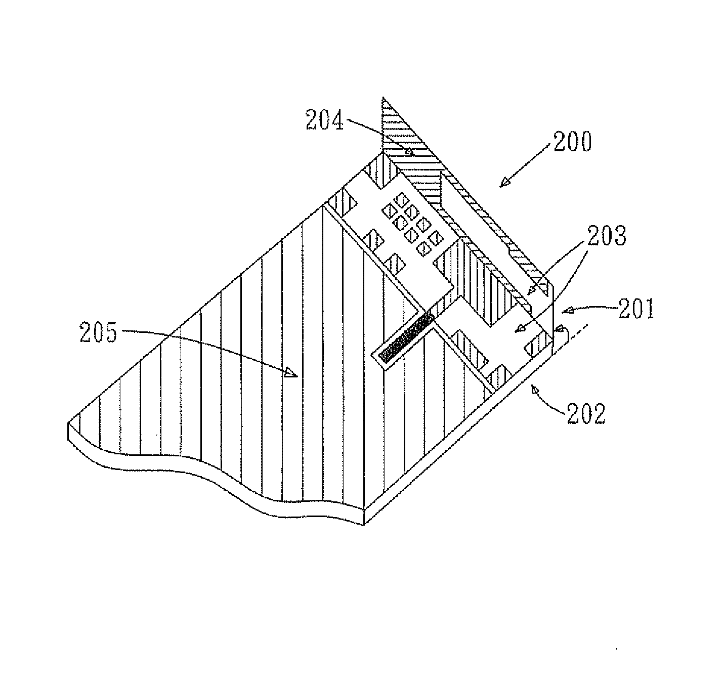
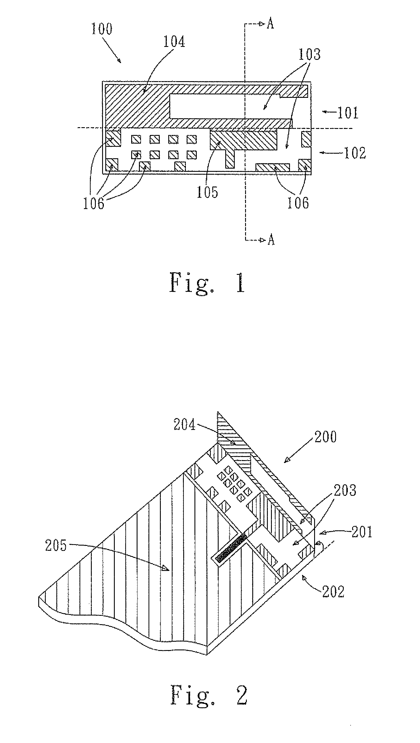
[0027]In a preferred embodiment of the present invention, a flexible antenna is essentially an electrical component much like a multi-lead IC or other surface mountable electronic components and is treated like one. FIG. 1 illustrates the ultra wide band antenna with no cable required for signal radio propagation in accordance with a preferred embodiment of the present invention.

[0028]A flexible antenna 100 of the present invention has a copper layer 104 patterned into the desired shape and geometry in the bottom side, the side of the antenna component 100 that faces toward the printed circuit board when it is assembled. This metallic pattern with its specific spatial geometry is typically shaped from half-ounce copper layer adhered to a substrate. Literally this copper l...


PUM

PropertyMeasurementUnit
frequenciesaaaaaaaaaa
lengthaaaaaaaaaa

Abstract

A multi-angle ultra wide band antenna for electronic devices is disclosed. The said antenna cover all mobile bands worldwide: 700 / 850 / 900 / 1700 / 1800 / 1900 and 2100 MHz and with sufficient bandwidth to include the 2400 and 2500 MHz mainly used in wireless networks, having a radiated element supported by a first substrate and expanding into a spatial geometry for transmission and reception of radio signal. An antenna base has a plurality of first solder pads on a second substrate for physical attachment to a printed circuit board and a second solder pad electrically connected to a terminal of said antenna to radio circuitry feed point, with compatible surface mount technology. The first and second substrates are joined by a bending line as a single substrate, where the said first substrate is allowed to be bent relative to the plane of the said second substrate.

Description

FIELD OF THE INVENTION[0001]The present invention relates in general to antennas, in particular to surface mount devices, and more particularly an antenna with a flexible body that can be bent on different angles and can be directly assembled to a printed circuit board by surface mount technique.BACKGROUND OF THE INVENTION[0002]Extensive efforts have been devoted to research and develop an antenna that can be used throughout the world, covering all the current cellular bands and complying with all communication standards, plus having the convenient surface mount technique for low cost and high reliability.[0003]Cellular and mobile devices are now operating with quad-band antennas, these bands are the 850 (GSM), 900 (EGSM), 1800 (DCS) and 1900 MHz (PCS), but with the introduction of 3G and 4G technologies for higher speed and data transfer rate in cellular applications, three new bands are introduced in the radiofrequency spectrum, 700 (LTE), 1700 (UMTS) and the 2100 MHz (WCDMA), but...

Claims


Application Information

Patent Timeline
Patent Type & Authority Patents(United States)
IPC IPC(8): H01Q1/24H01Q1/38H01Q1/20
CPCH01Q1/38H01Q9/42H01Q5/0051H01Q5/0017H01Q1/243Y10T29/49018H01Q5/25H01Q5/357
Inventor FLORES-CUADRAS, JAVIER RUBENO'SHEA, DERMOT O'SHEAQUINLAN, RONAN
Owner TAOGLAS GROUP HLDG LTD
Why Eureka
Try Eureka