
System and method for detecting blocked pitot-static ports

a pitot-static port and detection system technology, applied in the field of aviation electronics, can solve the problems of affecting the accuracy, serious affecting the accuracy of the determined air speed, altitude or other measured air data parameters, and pitot ports are especially vulnerable to blockag

Active Publication Date: 2014-05-06
ROSEMOUNT AEROSPACE
View PDF10 Cites 9 Cited by
  • Summary
  • Abstract
  • Description
  • Claims
  • Application Information

AI Technical Summary

Benefits of technology

The patent describes an air data computer that can use two different electrical signals to calculate two different measurements of aircraft movement. The first measurement is used to determine the main thrust of the aircraft, while the second measurement is used to determine the side-to-side movement of the aircraft. This allows for more accurate information about the aircraft's movement and helps to ensure safe and successful navigation.

Problems solved by technology

The pitot tube(s), static ports, and other associated ports, of an air data system can sometimes develop blockages which seriously affect the accuracy of the sensed pressures, and therefore seriously affect the accuracy of the determined air speed, altitude, or other measured air data parameters.
Pitot ports are especially vulnerable to blockage because the pitot opening is forward facing and is therefore the most susceptible to icing or ingestion of foreign material.
There is currently no reliable system and method for detecting whether a pitot tube and / or static port is either malfunctioning or is indeed blocked by any of the aforesaid debris.
Thus, multiple common mode failures may make it difficult or impossible to determine which, if any, systems are still operating correctly.
Further, current technology cannot distinguish between a blocked port and a problem associated with the pressure sensor and may also incorrectly vote out a properly functioning pressure measurement if two or more channels are in error by approximately the same amount.

Method used


Image

  • System and method for detecting blocked pitot-static ports
  • System and method for detecting blocked pitot-static ports
  • System and method for detecting blocked pitot-static ports

Examples


Embodiment Construction

[0015]The present invention is now described more fully with reference to the accompanying drawings, in which an illustrated embodiment of the present invention is shown. The present invention is not limited in any way to the illustrated embodiments as the illustrated embodiments described below are merely exemplary of the invention, which can be embodied in various forms, as appreciated by one skilled in the art. Therefore, it is to be understood that any structural and functional details disclosed herein are not to be interpreted as limiting, but merely as a basis for the claims and as a representative for teaching one skilled in the art to variously employ the present invention. Furthermore, the terms and phrases used herein are not intended to be limiting but rather to provide an understandable description of the invention.

[0016]The subject invention, and as discussed below with reference to the illustrated embodiments, is directed to a new and useful system and process for augm...


PUM

PropertyMeasurementUnit
frequencyaaaaaaaaaa
pressureaaaaaaaaaa
movementaaaaaaaaaa

Abstract

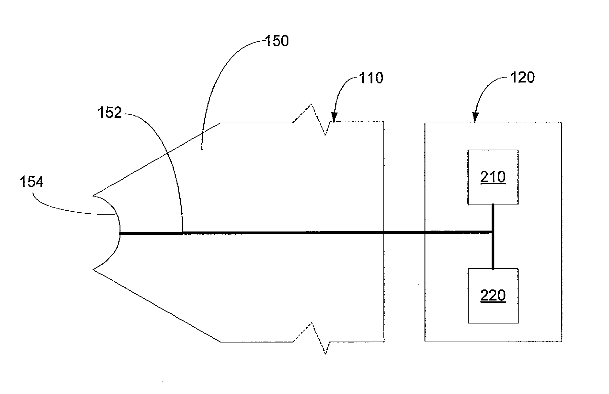
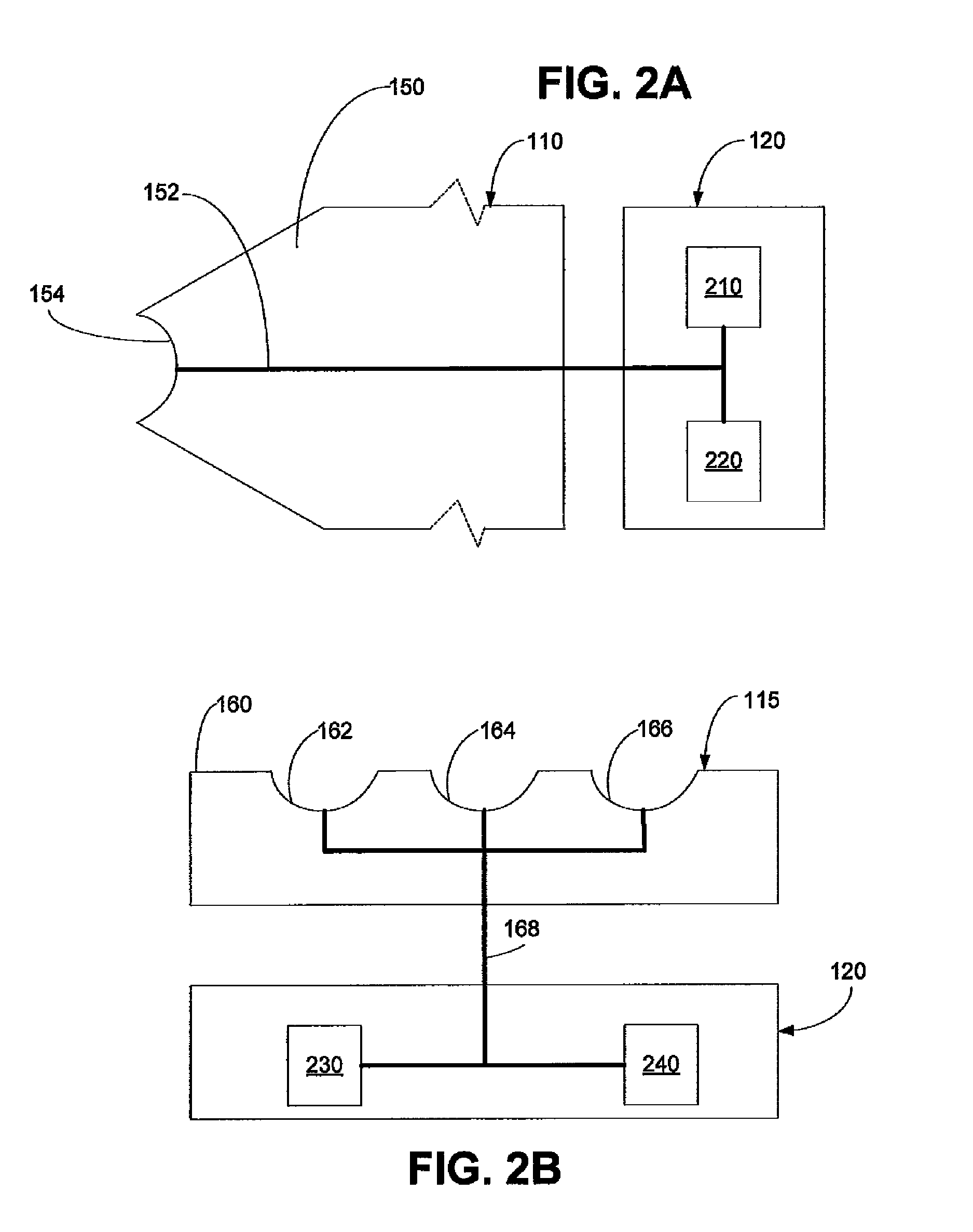
An avionics system and process for detecting pneumatic blockages having an air pressure measurement system including a first sensor positioned in association with the air inlet of an air probe component. The air pressure measurement system having a second sensor positioned in association with the air inlet for detecting air pressure in which the second sensor has a frequency response higher than that of the first sensor. An air data computer is coupled to each of the first and second sensors being configured and operable to calculate a first aircraft movement measurement using detected air pressure from the first sensor and is further operative to determine if the first sensor is faulty or if the air inlet is blocked in dependence upon the frequency content and amplitude of the output from the second sensor.

Description

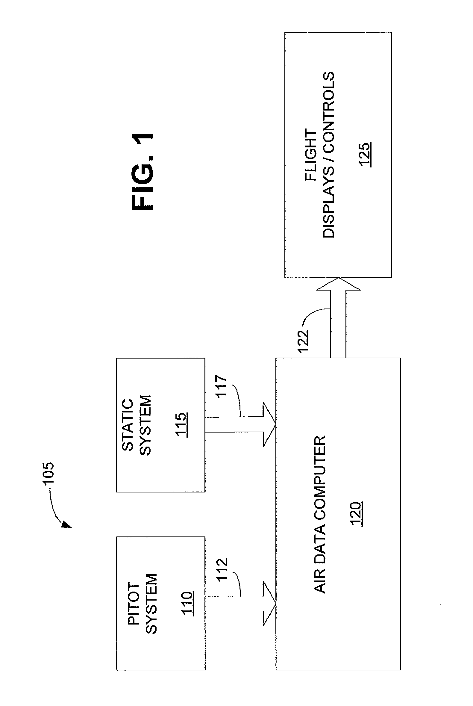
FIELD OF THE INVENTION[0001]The present invention relates to aviation electronics. More particularly, the present invention relates to methods and apparatus for identifying blocked pitot tubes, static ports, or other pressure ports of the air data system of an aircraft.BACKGROUND OF THE INVENTION[0002]Aircraft typically include air data systems which are used to determine the longitudinal air speed, and the altitude of the aircraft. Frequently these systems are also used to measure angle of attack, and angle of sideslip. The pitot system includes one or more pitot tubes which project out, of the airframe, into the air stream, and allow the impact pressure of the atmosphere to enter the tube(s). The pitot tube has an opening, generally circular, facing forward. The opening is exposed to rain air pressure while the aircraft is moving through the air. Sensors sense a pressure differential which can be between the impact air pressure from the pitot tube and static air pressure from a st...

Claims


Application Information

Patent Timeline
Patent Type & Authority Patents(United States)
IPC IPC(8): G01L7/00
CPCG01P5/165G01P13/025G01P21/025
Inventor GOLLY, TIMOTHY T.DEBO, JASON
Owner ROSEMOUNT AEROSPACE
Learn More