Vehicle collision protection apparatus

a technology for collision protection and vehicles, applied in vehicular safety arrangments, roofs, bumpers, etc., can solve the problems of difficult to avoid the problems described above, and the options are limited to enable backward displacement of high-current heaters

Inactive Publication Date: 2014-05-13
NISSAN MOTOR CO LTD
View PDF33 Cites 12 Cited by
  • Summary
  • Abstract
  • Description
  • Claims
  • Application Information

AI Technical Summary

Benefits of technology

[0009]Also, increased performance and increased functionality of vehicles have resulted in less available space in the front-rear direction in the engine compartment in vehicles equipped with an internal combustion engine, or in the motor compartment in an electric vehicle. Thus, there is no significant reduction of backward displacement of a high-mass body during a collision in the configuration proposed in Japanese Unexamined Patent Application Publication No. 2005-104354, since there is little initial available space for enabling backward displacement of a high-mass body.
[0011]Thus, the problems described above are difficult to avoid when backward displacement of a high-mass body during a collision is permitted. Therefore, an object of the present invention is to provide a vehicle collision safety apparatus that enables a high-mass body to rotate, for example, so as to deflect sideways in the vehicle during a collision. The high-mass body is thereby prevented or restricted from penetrating into the vehicle occupant space, such as the passenger compartment.

Problems solved by technology

Thus, there is no significant reduction of backward displacement of a high-mass body during a collision in the configuration proposed in Japanese Unexamined Patent Application Publication No. 2005-104354, since there is little initial available space for enabling backward displacement of a high-mass body.
Thus, even less options are available for enabling backward displacement of a high-current heater.
Thus, the problems described above are difficult to avoid when backward displacement of a high-mass body during a collision is permitted.

Method used


Image

  • Vehicle collision protection apparatus
  • Vehicle collision protection apparatus
  • Vehicle collision protection apparatus

Examples


Embodiment Construction

[0029]Selected embodiments will now be explained with reference to the drawings. It will be apparent to those skilled in the art from this disclosure that the following descriptions of the embodiments are provided for illustration only and not for the purpose of limiting the invention as defined by the appended claims and their equivalents.

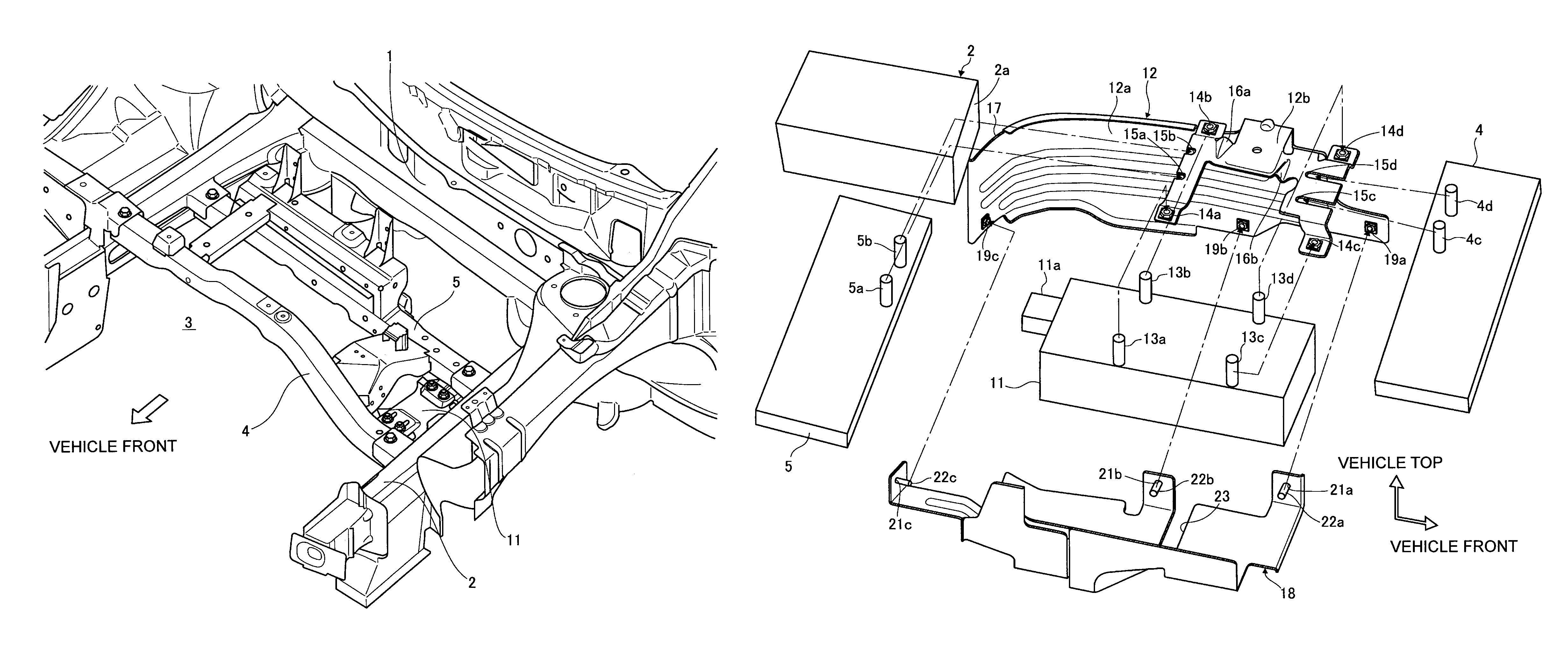
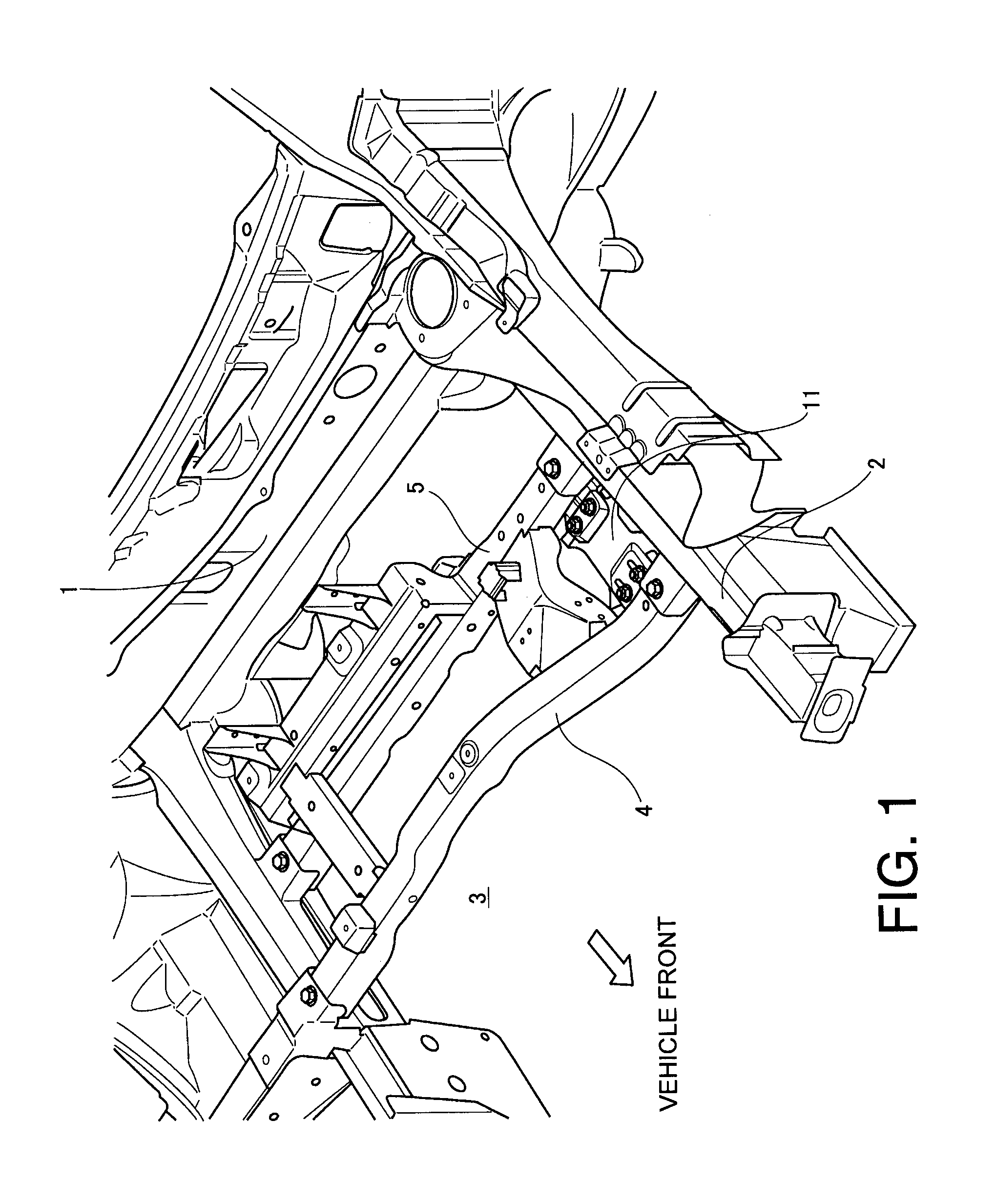
[0030]FIG. 1 is a perspective view taken from above the left side of a vehicle showing a portion of the frame of the vehicle body front of the vehicle that is provided with a collision protection apparatus according to a disclosed embodiment. In this example, the vehicle can be an electric vehicle or a hybrid vehicle, such as a car, truck, van, SUV and so on. A vehicle front space can be defined by a dash lower panel 1, a left front side member 2, a right front side member which is on the opposite side and not shown, and a front grille also not shown. Thus, the dash lower panel 1, the left front side member 2, the right front side member and the f...


PUM


Abstract

A vehicle collision protection apparatus includes a bracket. The bracket includes a deflecting force generating component provided at a rear end of the bracket. The bracket is disposed in a vehicle front space of a vehicle and extends in a front to rear direction of the vehicle and attach a vehicle component to a body of the vehicle. The deflecting force generating component deflects the rear end of the bracket in a width direction of the vehicle and rotates the bracket together with the vehicle component in the width direction when the deflecting force generating component impinges against a portion of the vehicle body as the rear end of the bracket is displaced in a rearward direction of the vehicle due to crushing of a front end of the vehicle during a collision at the front end of the vehicle.

Description

CROSS-REFERENCE TO RELATED APPLICATIONS[0001]This application is a U.S. National stage of International Application No. PCT / IB2011 / 000913, filed Apr. 28, 2011. This application claims priority to Japanese Patent Application No. 2010-112960, filed on May 17, 2010. The entire disclosure of Japanese Patent Application No. 2010-112960 is hereby incorporated herein by reference.BACKGROUND[0002]1. Field of the Invention[0003]The present invention generally relates to a vehicle collision protection apparatus. More particularly, the present invention relates to a vehicle collision protection apparatus for restricting movement of an object present in a space at the front of a vehicle into a vehicle occupant space during a frontal collision[0004]2. Background Information[0005]In a typical vehicle, such as a car, truck, van, SUV and so on, certain main components are accommodated in a space under the hood at the front of a vehicle. These main components can include, for example, the engine, th...

Claims


Application Information

Patent Timeline
Patent Type & Authority Patents(United States)
IPC IPC(8): B60J7/00
CPCB60H1/2209B60H2001/2293B62D21/152B62D25/082B62D21/00B62D21/15
Inventor OYAMA, HIROSHISHIMADA, JUNICHISAWAKI, MIKITO
Owner NISSAN MOTOR CO LTD
Why Eureka
Try Eureka