Switching device with improved tripping action in the event of a short circuit

a technology of short circuit and switching device, which is applied in the direction of air-break switch, high-tension/heavy-dress switch, electrical apparatus, etc., can solve the problems of no longer being able to have an off-center impact, and achieve the effect of avoiding jamming, high switching capacity, and preventing melting of structures within the switching chamber

Active Publication Date: 2017-05-23
SIEMENS AG
View PDF13 Cites 0 Cited by
  • Summary
  • Abstract
  • Description
  • Claims
  • Application Information

AI Technical Summary

Benefits of technology

[0025]A prior art switching device of the type herein taught, in particular when used as a power switch with high switching capacity, is characterized in that less room is available for bridge guidance in order to always align the bridge in the center of the chamber. Due to the increased forces that throw the bridge in the event of a short circuit, and as a result of a potentially non-central position of the bridge, the bridge can become jammed in the lower part, as a result of which the device can no longer be switched on. Through the provision of centering structures in accordance with the present invention, however, the bridge always meets the impact dome symmetrically, and jamming is avoided. A further advantage provided by the present invention is that by virtue of the centering structures, the bridge is aligned centrally during the course of its movement, and thereby always maintains adequate distance from the chamber walls when in the off position. Melting of structures within the switching chamber is thus prevented.

Problems solved by technology

An off-center impact is thus no longer possible, and the bridge cannot become twisted.

Method used


Image

  • Switching device with improved tripping action in the event of a short circuit
  • Switching device with improved tripping action in the event of a short circuit
  • Switching device with improved tripping action in the event of a short circuit

Examples


Embodiment Construction

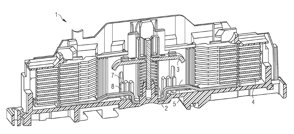
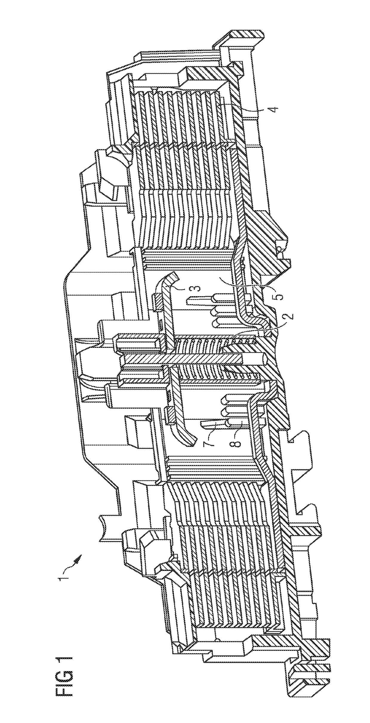
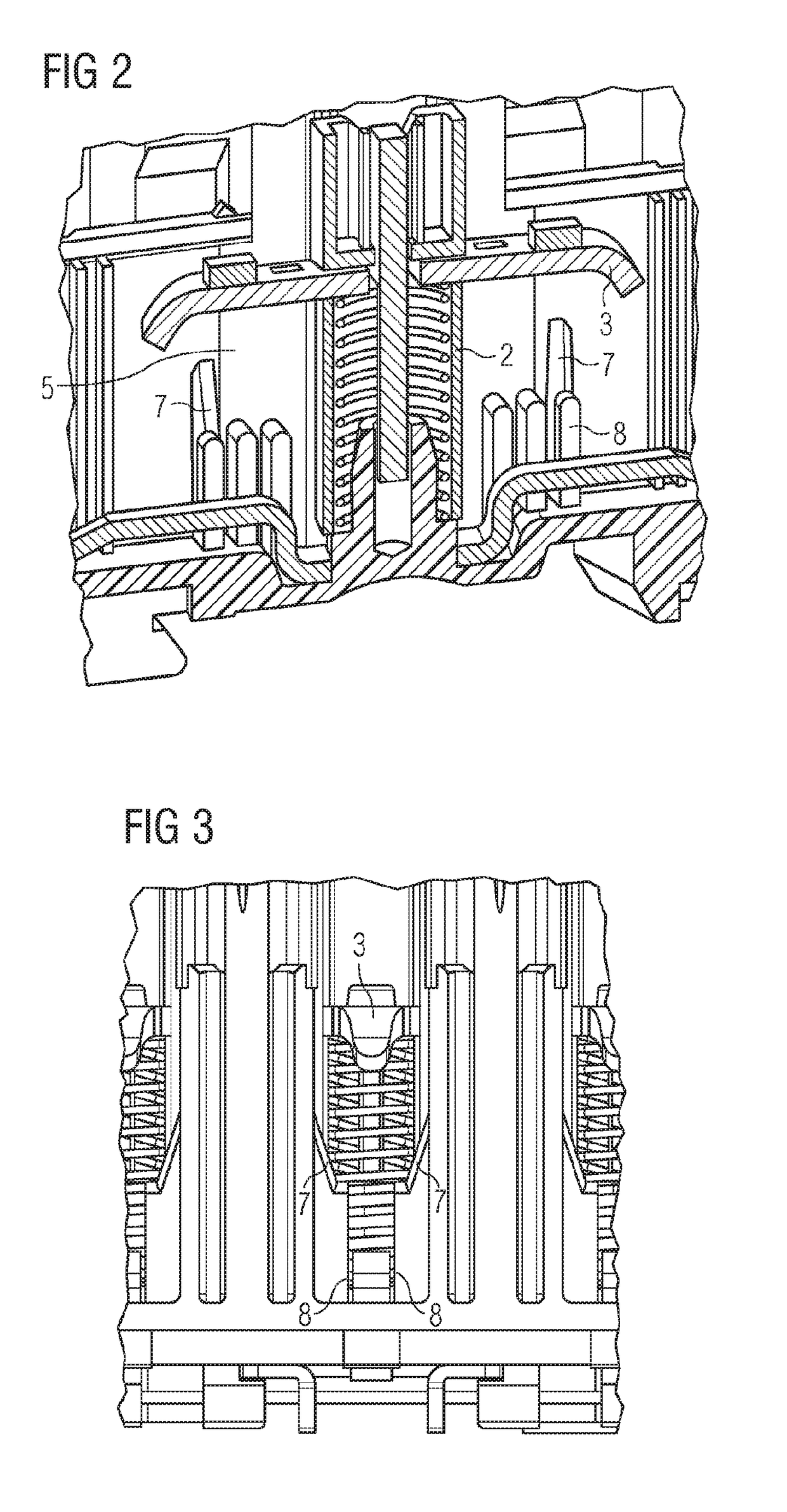
[0033]FIG. 1 shows a cross-sectional view of a switching device, in particular of a power switch with an arc quenching chamber 1, constructed in accordance with the invention and in which a sliding contact 2 is arranged and a movable contact element 3 is guided for movement. Arranged on both the left and right sides of, and next to, the movable contact element 3 are arc quenching baffle packages 4 each formed of plural arc quenching baffles disposed in parallel relation above one another. Centering structures 7 of the invention are provided on a housing wall 5 of arc quenching chamber 1 in the region of movable contact element 3.

[0034]The centering structures 7 are preferably fabricated as a single piece with housing wall 5 of the arc quenching chamber, which is to say that the centering structures 7 are not formed as an additional part on the housing wall 5 but, rather, are injection-molded together with the housing wall 5 in one process step. The centering structures 7 are accordi...


PUM


Abstract

A switching device having an arc quenching chamber, a fixed contact element and a movable contact element movable in a sliding contact between untripped and tripped positions within the chamber. A plurality of centering structures are arranged on the walls of the arc quenching chamber for centered guiding movement of the movable contact element as it moves from its untripped position to its tripped position. The centering structures may be fabricated unitarily with the chamber walls, as of plastic, and are arranged in parallel and spaced apart relation to one another.

Description

FIELD OF THE INVENTION[0001]The present invention relates to a switching device with an arc quenching chamber in which is disposed a contact arrangement formed of a fixed contact element and a movable contact element, wherein the movable contact element is guided for movement in a sliding contact.BACKGROUND OF THE INVENTION[0002]Switching devices, in particular power switches, are used for amongst other things safely switching off power in the event of a short circuit, thus protecting loads and installations. Electrical or mechanical switching devices are also suitable for operationally correct manual switching of loads and for safe disconnection of an installation from the power grid during servicing work or modifications to the installation. Electrical switching units are often operated electromagnetically.[0003]As a consequence, switching units of this type are highly technical electrical switching devices with integrated protection for motors, cables, transformers and generators...

Claims


Application Information

Patent Timeline
Patent Type & Authority Patents(United States)
IPC IPC(8): H01H33/02H01H9/34H01H71/02
CPCH01H33/02H01H9/346H01H2071/0292
Inventor STEINBAUER, MARTIN
Owner SIEMENS AG
Why Eureka
Try Eureka