Filter bandwidth adjustment in a multi-loop dimmer control circuit

a filter bandwidth and control circuit technology, applied in the direction of electric variable regulation, process and machine control, instruments, etc., can solve the problems of overshoot or undershoot of led load current provided, limited bandwidth of led load current control loop, and low response time, so as to reduce loop signal noise and potential led flickering, reduce loop signal noise and reduce loop signal

Active Publication Date: 2014-05-13
DIALOG SEMICONDUCTOR INC
View PDF8 Cites 4 Cited by
  • Summary
  • Abstract
  • Description
  • Claims
  • Application Information

AI Technical Summary

Benefits of technology

[0008]When one of the dimmer or the constant current loop is driving the signal generator, the bandwidth of the driving loop filter is reduced, for instance to a pre-determined minimum, in order to reduce loop signal noise and potential LED flickering. At the same time, the bandwidth of the non-driving loop (or inactive loop) filter is increased to a pre-determined maximum, in order to improve response time and reduce potential overshoot or undershoot during dimmer adjustment.
[0009]When a dimmer output signal is received indicating a requested increase in brightness while the dimmer loop is driving the signal generator, the dimmer control circuit can increase the dimmer loop filter bandwidth while maintaining the constant current loop filter bandwidth. When the requested increase in brightness causes the first loop signal to be larger than the second loop signal, the dimmer control circuit switches from dimmer loop operation to constant current loop operation, increases the dimmer loop filter bandwidth to a pre-determined maximum and decreases the constant current loop bandwidth from a pre-determined maximum.
[0010]Similarly, when a dimmer output signal is received indicating a requested decrease in brightness while in constant current loop operation, the dimmer control circuit can increase the constant current loop filter bandwidth while maintaining the dimmer loop filter bandwidth. When the requested decrease in brightness causes the second loop signal to be larger than the first loop signal, the dimmer control circuit switches from constant current loop operation to dimmer loop operation, increases the constant current loop bandwidth to a pre-determined maximum and decreases the dimmer loop bandwidth from a pre-determined maximum.

Problems solved by technology

However, in order to maintain stability in such an implementation, the bandwidth in the LED load current control loop is limited.
As a result, the dimming response can be sluggish, for instance upon a rapid dimmer level adjustment.
Switching between driving the power circuit based on the dimmer signal and the current reference can also be sluggish, and may result in overshoot or undershoot of LED load current provided by the power circuit.
While the power circuit will correct the load current overshoot or undershoot eventually, the LED itself can flicker or produce other undesirable effects in the meantime as a result of the sporadic load current behavior.

Method used


Image

  • Filter bandwidth adjustment in a multi-loop dimmer control circuit
  • Filter bandwidth adjustment in a multi-loop dimmer control circuit
  • Filter bandwidth adjustment in a multi-loop dimmer control circuit

Examples


Embodiment Construction

[0017]The Figures (FIG.) and the following description relate to various embodiments by way of illustration only. It should be noted that from the following discussion, alternative embodiments of the structures and methods disclosed herein will be readily recognized as viable alternatives that may be employed without departing from the principles discussed herein.

[0018]Reference will now be made in detail to several embodiments, examples of which are illustrated in the accompanying figures. It is noted that wherever practicable similar or like reference numbers may be used in the figures and may indicate similar or like functionality. The figures depict various embodiments for purposes of illustration only. One skilled in the art will readily recognize from the following description that alternative embodiments of the structures and methods illustrated herein may be employed without departing from the principles described herein.

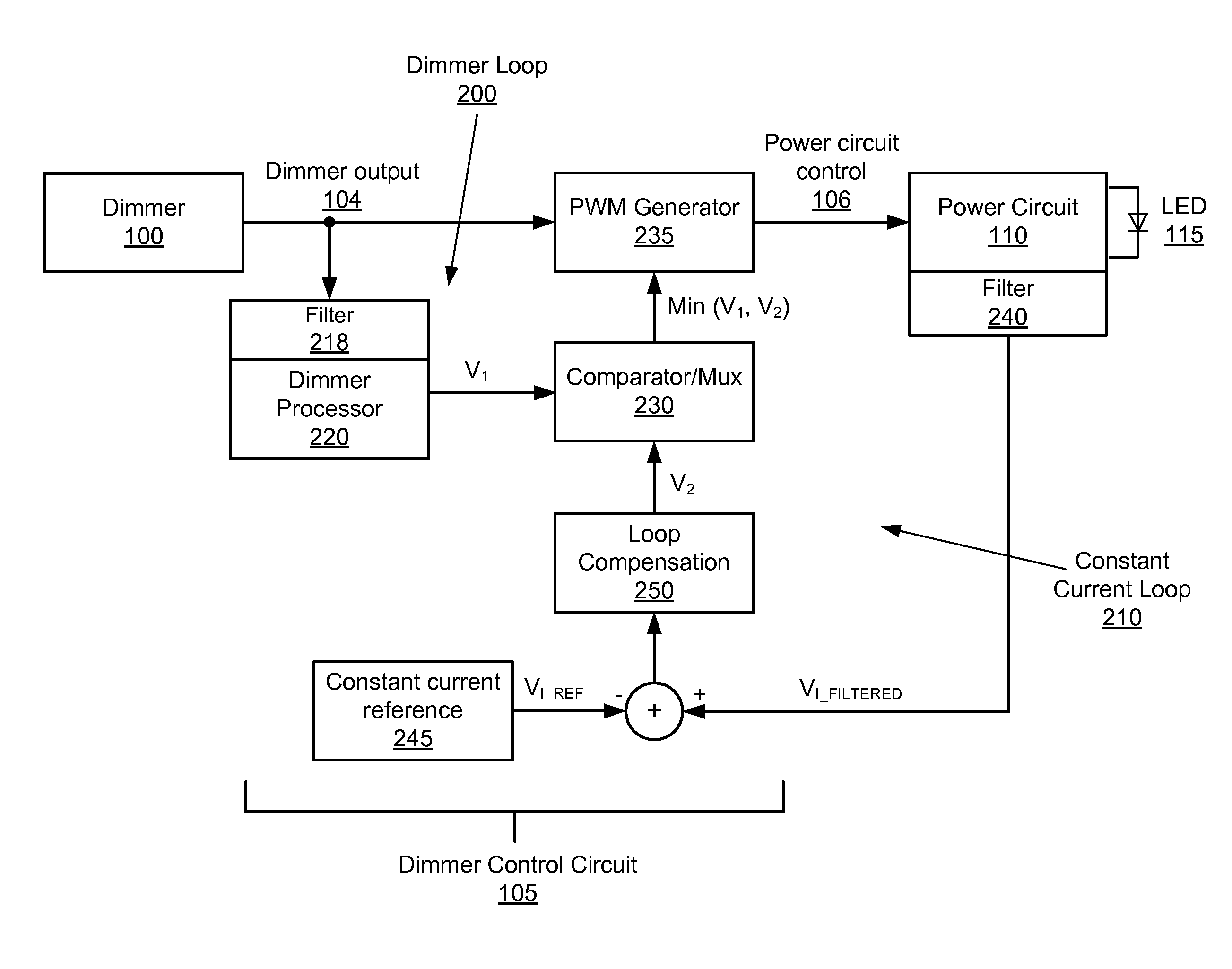
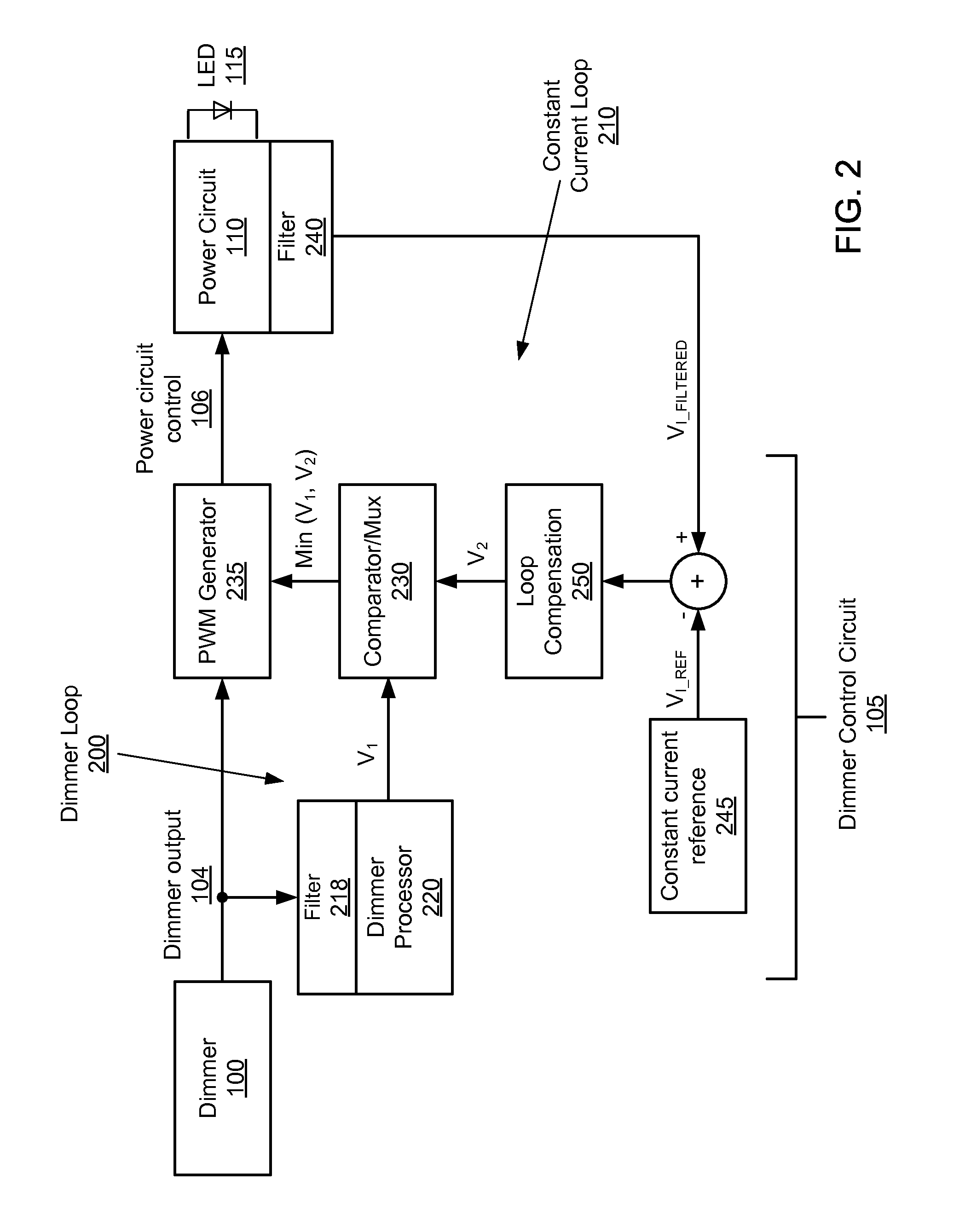
[0019]Embodiments disclosed herein describe the settin...


PUM


Abstract

The embodiments disclosed herein describe the adjusting of filter bandwidths in a multi-loop LED dimmer control circuit based on received dimmer input signals. The bandwidth of a filter in an active loop (a loop driving an LED power circuit) is decreased to prevent signal noise and associated LED flickering. Likewise, the bandwidth of a filter in an inactive loop (a loop not driving the LED power circuit) is increased to a pre-determined maximum in order to improve response time and decrease potential overshoot or undershoot during dimmer adjustment.

Description

BACKGROUND[0001]1. Field of Technology[0002]Embodiments disclosed herein relate generally to LED operation and more specifically to filter bandwidth adjustment in a multi-loop LED dimmer control circuit.[0003]2. Description of the Related Arts[0004]Dimmable LED drivers generally perform two functions: regulating the LED load current based on a dimmer signal describing a level of LED brightness, and providing a constant load current if the dimmer signal describes a maximum level of brightness. In one implementation, a dimmer signal can directly modify a reference current in an LED load current control loop such that the load current varies with changes in the dimmer signal. However, in order to maintain stability in such an implementation, the bandwidth in the LED load current control loop is limited. As a result, the dimming response can be sluggish, for instance upon a rapid dimmer level adjustment.[0005]To improve dimming response performance, the dimmer signal can instead influen...

Claims


Application Information

Patent Timeline
Patent Type & Authority Patents(United States)
IPC IPC(8): H05B41/24H05B37/02H05B39/04H05B41/36H05B41/16G05F1/00H05B44/00
CPCH05B33/0815H05B33/0848H05B45/14H05B45/382H05B45/385
Inventor WANG, XIAOYANKESTERSON, JOHN WILLIAMPOON, CLARITA C.FENG, GUANGLI, HAIJU
Owner DIALOG SEMICONDUCTOR INC
Why Eureka
Try Eureka