Mounting system

a technology of mounting system and mounting bracket, which is applied in the direction of television system, furniture parts, machine supports, etc., can solve the problems of limited viewing and inability to provide comfortable viewing

Active Publication Date: 2014-05-13
MANEHU PROD ALLIANCE LLC
View PDF57 Cites 62 Cited by
  • Summary
  • Abstract
  • Description
  • Claims
  • Application Information

AI Technical Summary

Benefits of technology

[0006]At least some embodiments are directed to mounts capable of holding and moving objects. Mounted objects can be held at relatively high locations to keep the objects out of the way when stowed. Mounted objects can be conveniently moved to a desired position.

Problems solved by technology

Unfortunately, if tilting wall mounts are installed at relatively high locations, there may be limited viewing because ideal viewing often requires that the center of the screen be level with a viewer's eyes.
If either a tilting wall mount or a full motion wall mount is installed above a fireplace, the mounted television is often much higher than a sitting viewer's eyes and, thus, may not provide comfortable viewing.

Method used


Image

  • Mounting system
  • Mounting system
  • Mounting system

Examples


Embodiment Construction

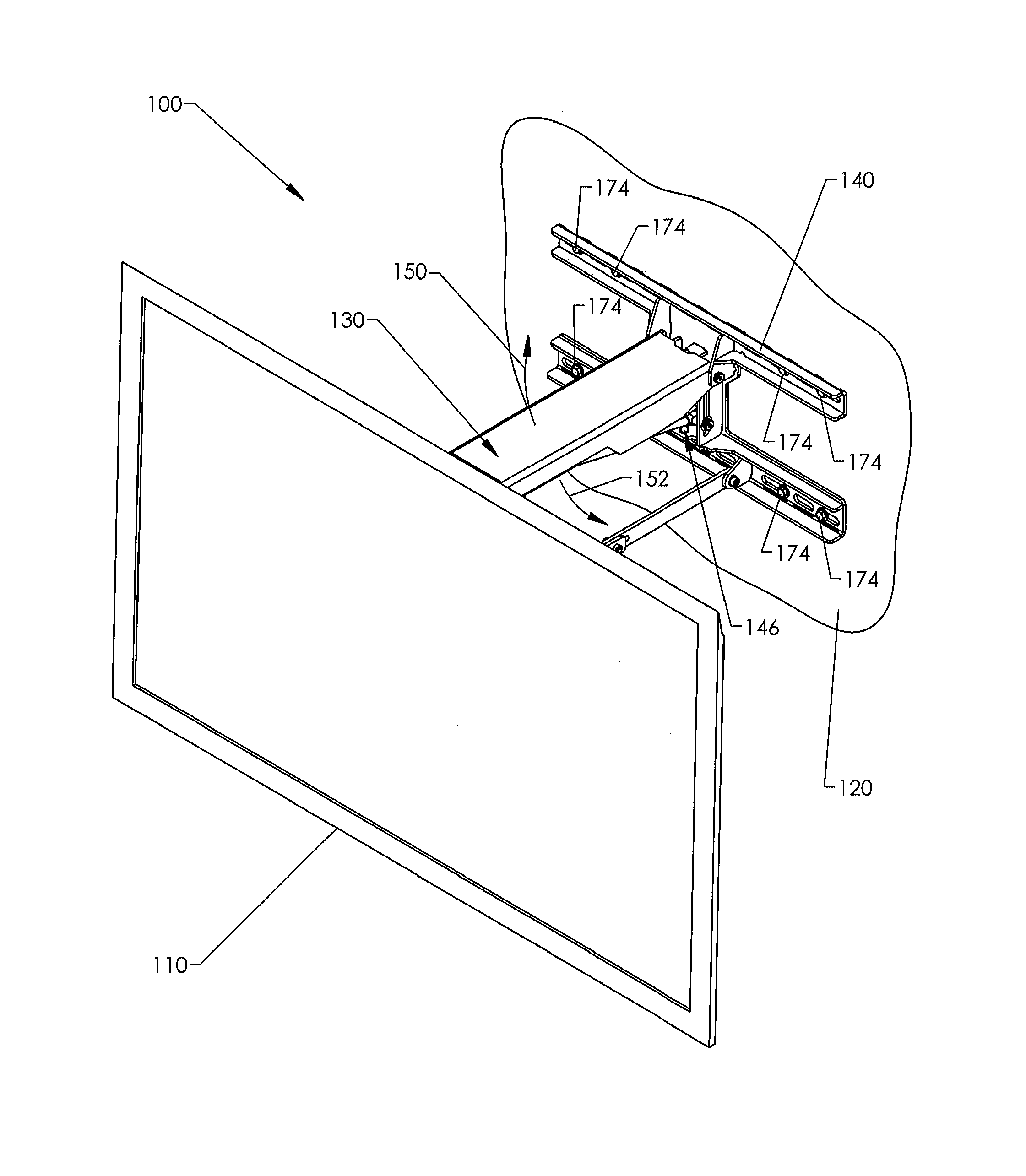
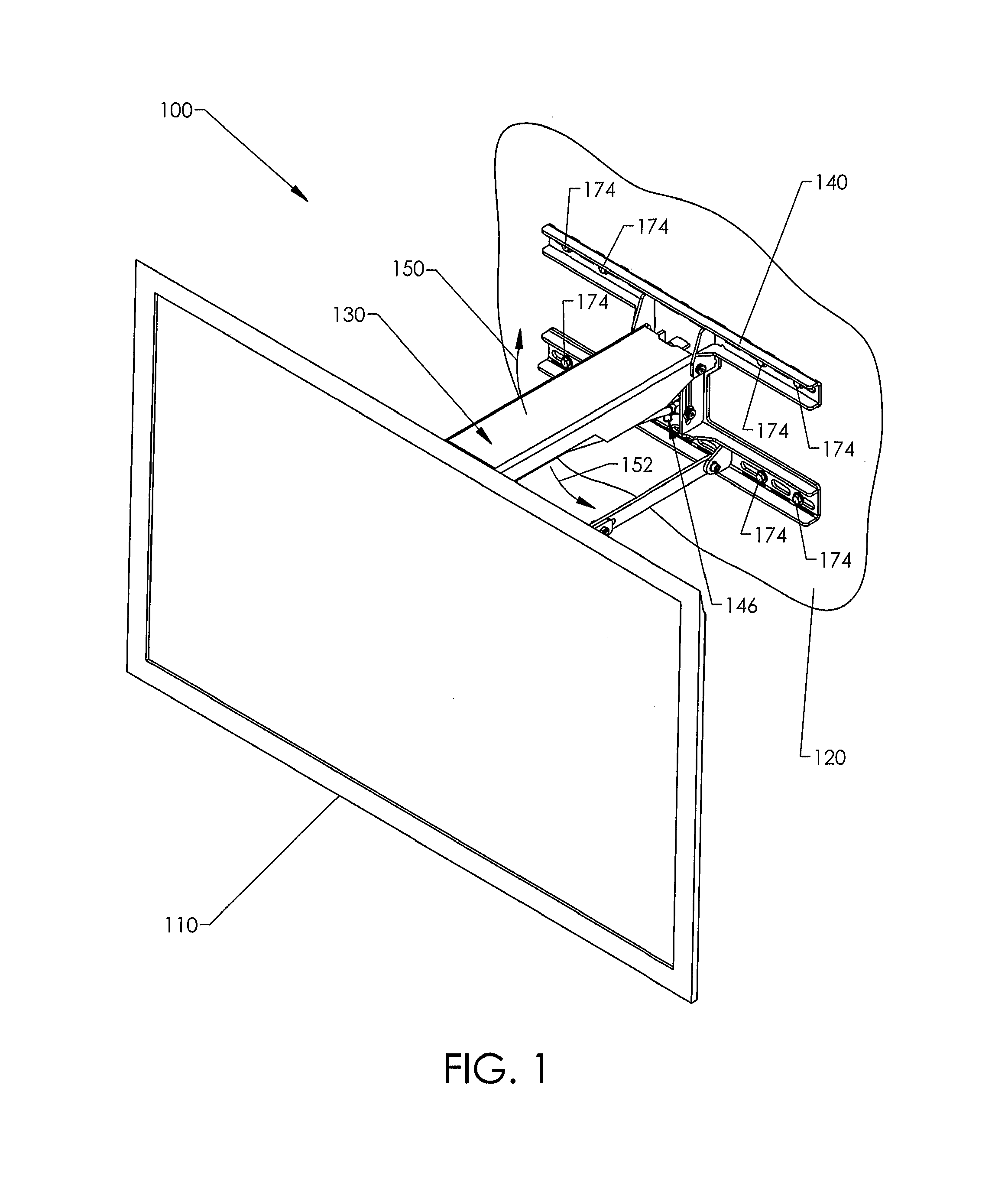
[0049]FIG. 1 shows a mounting system in the form of a wall mount 100 carrying an electronic display in the form of a flat screen television 110. A collapsible linkage assembly 130 is connected to a support bracket 140 that is mounted to a support structure in the form of a wall 120. The linkage assembly 130 can swing upwardly (indicated by an arrow 150) or downwardly (indicated by an arrow 152). An adjustment mechanism 146 is operable to adjust a biasing force provided by a biasing mechanism to allow for controlled movement of the television 110. Once the television 110 is at a desired position, the biasing mechanism keeps the television 110 stationary.

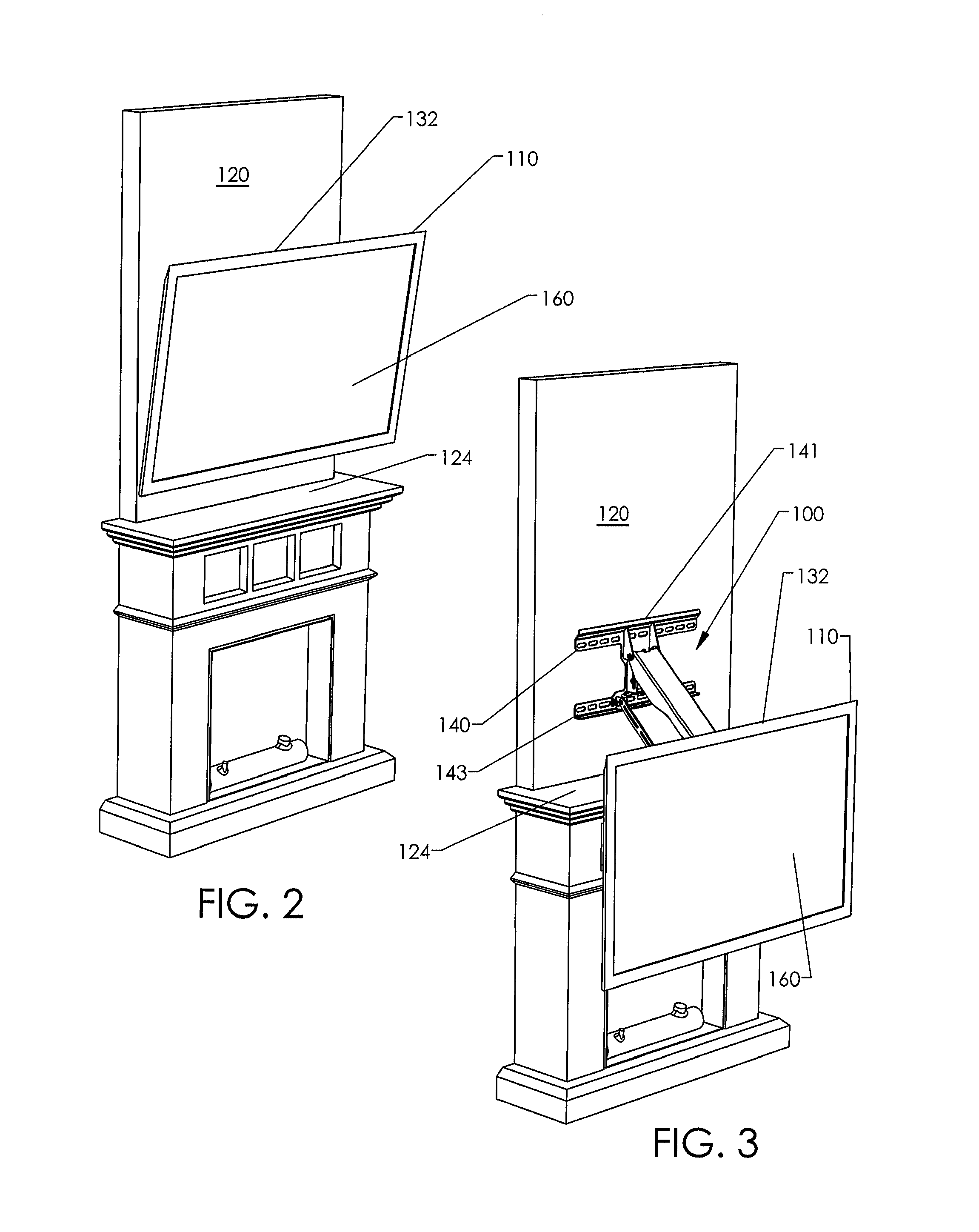
[0050]FIG. 2 shows the television 110 in a raised, stowed position and very close to the wall 120. The wall mount 100 is hidden from view of someone in front of the television 110 for an aesthetically pleasing appearance. Advantageously, it may be difficult for small children to reach up and pull down on the television 110. The illust...


PUM


Abstract

A mounting system capable of mounting objects to support structures. The mounting system includes a wall mount including a display bracket configured to hold the object, a fixed support bracket coupleable to a vertical support structure, and a linkage assembly. The linkage assembly has a low-profile stowed configuration in which the object is held in a raised position close to the support structure. The linkage assembly moves to another configuration to move the object. The object can be held in a lowered position. A biasing mechanism can facilitate convenient movement of the object.

Description

CROSS-REFERENCE TO RELATED APPLICATION[0001]This application claims the benefit under 35 U.S.C. §119(e) of U.S. Provisional Patent Application No. 61 / 396,850 filed Jun. 4, 2010. This provisional application is incorporated herein by reference in its entirety.BACKGROUND[0002]1. Technical Field[0003]The present invention relates generally to mounting systems. More specifically, the invention relates to mounting systems for mounting objects to structures.[0004]2. Description of the Related Art[0005]Televisions are often mounted directly to walls using wall mounts. Tilting wall mounts and full motion wall mounts are two types of mounts that allow movement of the television. Tilting wall mounts often allow tilting about a horizontal axis of rotation. Unfortunately, if tilting wall mounts are installed at relatively high locations, there may be limited viewing because ideal viewing often requires that the center of the screen be level with a viewer's eyes. Full motion wall mounts often al...

Claims


Application Information

Patent Timeline
Patent Type & Authority Patents(United States)
IPC IPC(8): H04N5/655
CPCH04N5/655H04N5/64F16M11/06F16M11/18F16M11/2014F16M11/2092F16M13/02F16M2200/044F16M2200/063A47B97/001F16M11/10
Inventor MASSEY, KURT, WILLIAM
Owner MANEHU PROD ALLIANCE LLC
Why Eureka
Try Eureka