Storage control device controlling refresh frequency based on temperature

a technology of temperature control and storage control device, which is applied in the direction of information storage, static storage, digital storage, etc., can solve the problem of requiring an increased number of wires, and achieve the effect of simplifying the wiring structur

Inactive Publication Date: 2014-05-13
SONY CORP
View PDF19 Cites 24 Cited by
  • Summary
  • Abstract
  • Description
  • Claims
  • Application Information

AI Technical Summary

Benefits of technology

[0007]The present invention has been made in light of the foregoing, and it is an aim of the present invention to provide a simpler wiring structure adapted to output temperature information from each memory in order to control a refresh in a manner appropriate to the temperature conditions of the plurality of memories.
[0019]The present invention is advantageous in providing a simpler wiring structure adapted to output temperature information from each memory in order to control refresh in a manner appropriate to the temperature conditions of the plurality of memories.

Problems solved by technology

However, this configuration requires an increased number of wires for supplying temperature information from each of the memory chips to the logic block.

Method used


Image

  • Storage control device controlling refresh frequency based on temperature
  • Storage control device controlling refresh frequency based on temperature
  • Storage control device controlling refresh frequency based on temperature

Examples


first embodiment (

1. First Embodiment (configuration in which each memory of the memory system is capable of receiving and outputting selected temperature information and integrated temperature information for refresh appropriate to temperature)

[0032]2. Second Embodiment (example in which configuration in which each memory of the memory system is capable of receiving and outputting selected temperature information and integrated temperature information for refresh appropriate to temperature is applied to a stacked memory system)

first embodiment

1. First Embodiment

Configuration for Receiving and Outputting Temperature Information between Memories of the Memory System

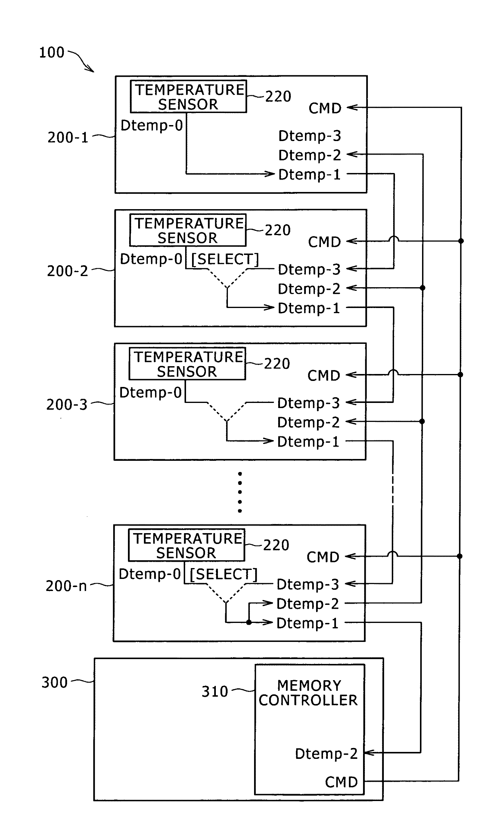
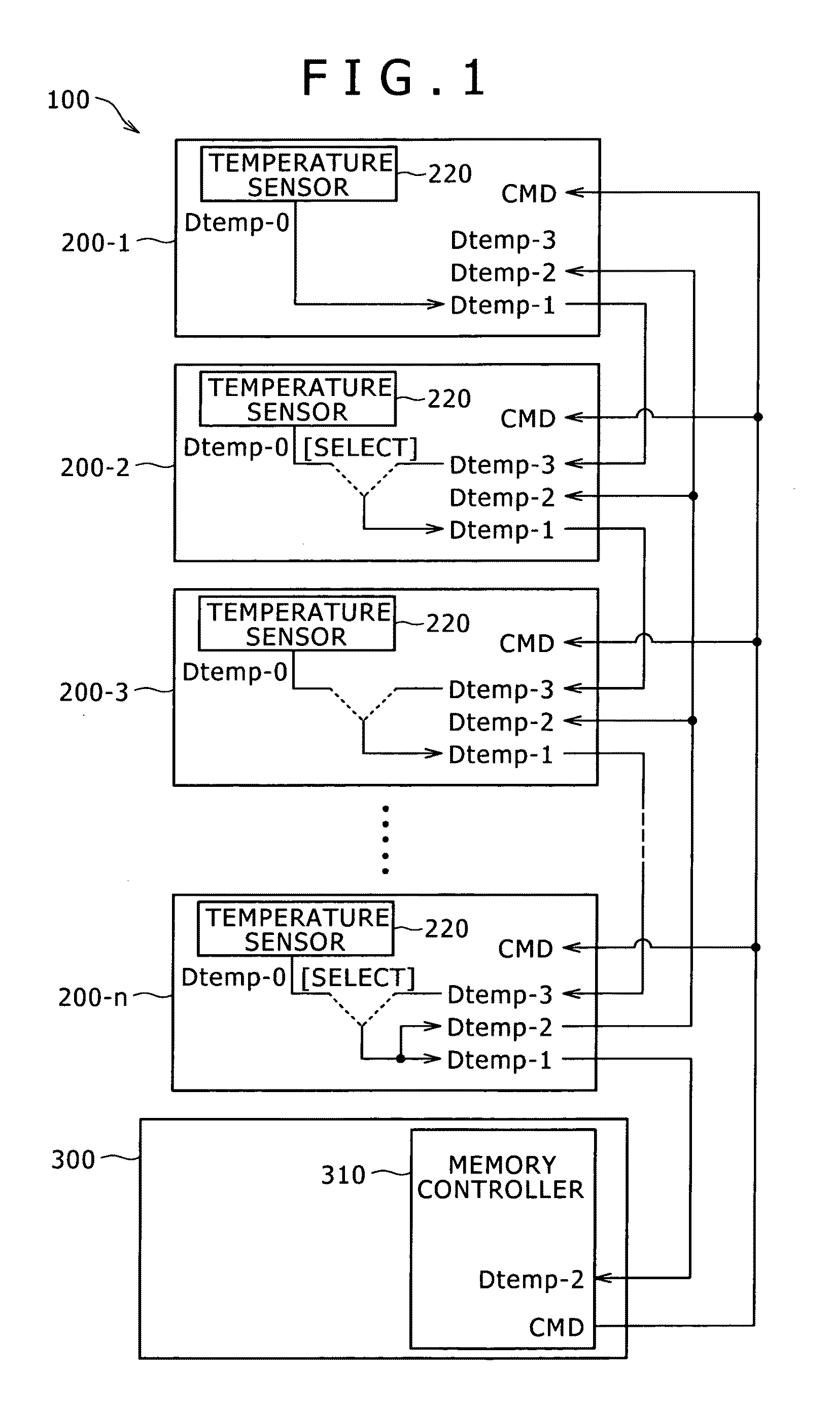
[0033]FIG. 1 illustrates an example of reception and output of temperature information in a memory system 100 according to an embodiment of the present invention that includes a plurality of memories.

[0034]The memory system 100 includes n memories, i.e., first to nth memories 200-1 to 200-n, and a logic block 300. In the present embodiment, each of the first to nth memories 200-1 to 200-n is physically formed, for example, as a discrete memory chip. Further, the logic block 300 is also formed as a chip. These chips are arranged at predetermined positions, for example, on a substrate. It should be noted that, in the description given below, the first to nth memories 200-1 to 200-n may be written as memories 200 if all or some thereof are treated collectively with no particular distinction.

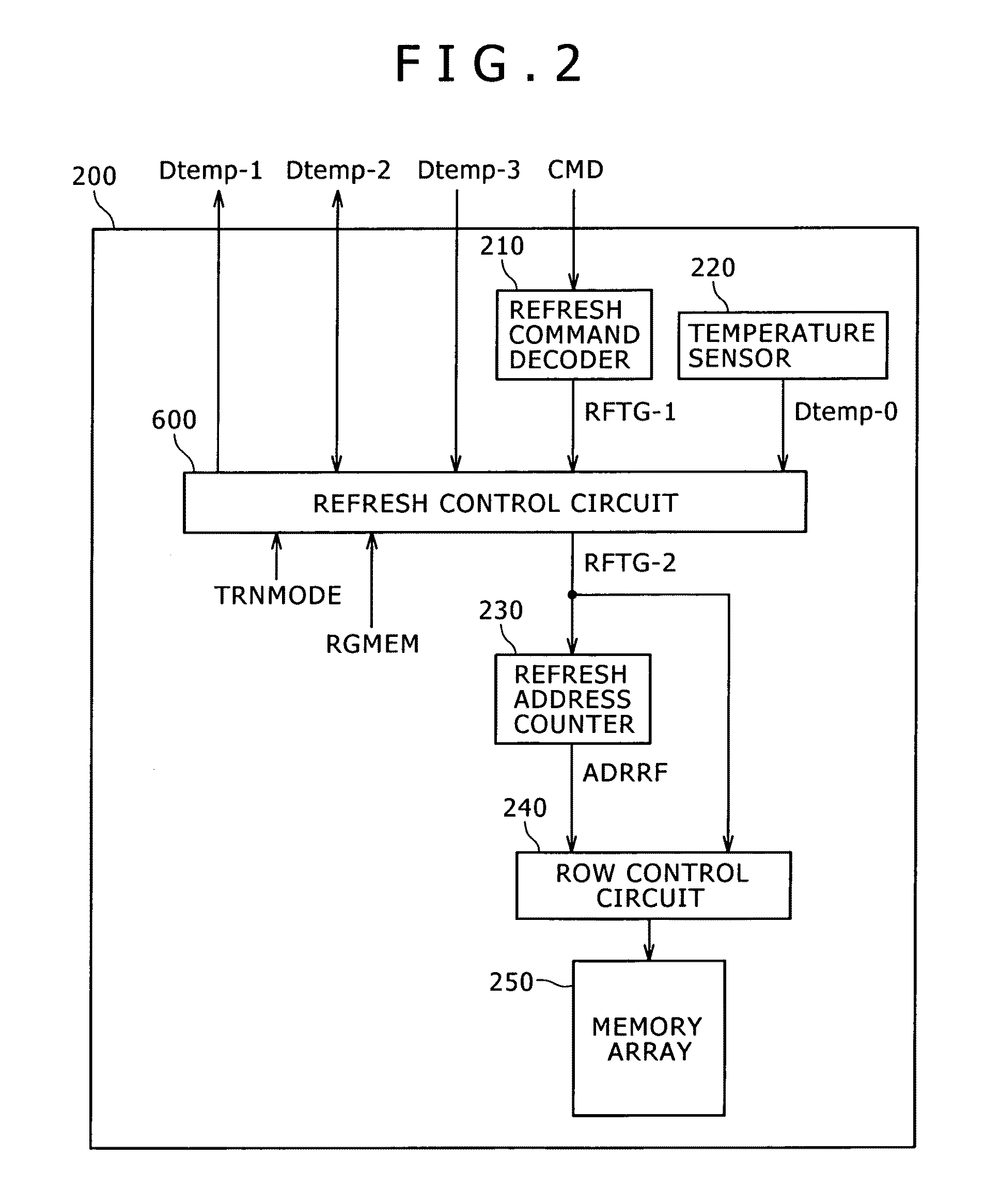
[0035]The memories 200 include, for example, a dynamic memory array and are...

second embodiment

2. Second Embodiment

Example of Outline of a Stacked Memory System

[0129]In the memory system 100 according to the present embodiment that has been described up to this point, there are no particular restrictions, for example, as to the physical layout of the memories 200 and logic block 300. For example, the layout of the chips of the memories 200 and logic block 300 at different positions in the plane direction is also included in the first embodiment of the present invention. In contrast, the second embodiment of the present invention is intended for a so-called stacked memory system in which the chips of the memories 200 and logic block 300 are stacked one on top of the others. Stacking permits, for example, significant physical size reduction of the module of the memory system 200.

[0130]FIG. 10 illustrates an example of physical layout of the memories 200 and logic block 300 as seen from the side as the stacked memory system 100 according to the second embodiment of the present i...


PUM


Abstract

Disclosed herein is a storage control device that includes a temperature sensor, temperature information selection section, refresh command reception section and trigger issuance frequency setting section.

Description

BACKGROUND OF THE INVENTION[0001]1. Field of the Invention[0002]The present invention relates to a storage control device, storage device and storage device system and, more particularly, to a storage control device, storage device and storage device system that control refresh according to the temperature conditions of dynamic memories.[0003]2. Description of the Related Art[0004]A dynamic memory stores information by the presence or absence of an electric charge held by capacitors. This type of memory requires a refresh that is composed of reading out the data stored in the memory and rewriting the data before the charge is lost due to a leak current. On the other hand, a leak current in a dynamic memory is known to have a temperature dependence which causes the leak current to diminish at low temperatures and increase at high temperatures.[0005]Therefore, when the refresh frequency is set according to the leak current flow at high temperatures, this frequency is excessively high ...

Claims


Application Information

Patent Timeline
Patent Type & Authority Patents(United States)
IPC IPC(8): G11C7/00G11C7/04G11C11/406
CPCG11C11/40626G11C11/406G11C11/40618G11C7/04
Inventor KURODA, MASAMI
Owner SONY CORP
Why Eureka
Try Eureka