Method and system for evaluating characteristics of an S-cam

a technology of characteristics and characteristics, applied in the direction of valve drives, machines/engines, instruments, etc., can solve the problems of uneven application of braking force between the two brake shoes, uneven wear of the brake components, uneven application of braking force, etc., to reduce the need for manual movement, the effect of effective application of the s-cam

Active Publication Date: 2014-05-13
BENDIKS SPAJSER FAUNDEJSHN BREJK LLK
View PDF6 Cites 1 Cited by
  • Summary
  • Abstract
  • Description
  • Claims
  • Application Information

AI Technical Summary

Benefits of technology

[0012]A method and system in accordance with the present invention are advantageous relative to conventional methods and systems because the inventive method and system evaluate one or more characteristics of S-cams that are not evaluated in conventional methods and systems and that the inventors have identified as contributing to the effective application of the S-cam. For example, the inventors have discovered that the deviation in the profile of the cam from a desired profile is insufficient, standing alone, to evaluate manufactured S-cams. In particular, a large change in the rate of deviation can lead to ineffective application of the cam even if the deviation of the cam profile from a desired profile is within acceptable limits. In addition, the inventive method and system are advantageous because they reduce and / or eliminate the need for manual movement and measurement of system components and manual computations.

Problems solved by technology

Deviation of the profile of either lobe of the S-cam from an optimal profile can lead to uneven application of braking force and uneven wear of braking components.
Deviation among the profiles for the two lobes can also result in uneven application of braking force among the two brake shoes.
Conventional methods and systems for inspecting S-cams suffer from several deficiencies.
As a result, the methods and systems are time consuming and relatively inaccurate.
Further, conventional methods and systems fail to account for one or more important characteristics of the S-cam identified by the inventors that contribute to effective application of the S-cam.
CMMs are typically general purpose devices and / or primarily directed to parts other than the S-cam, however, and fail to account for the various characteristics of the S-cam identified by the inventors that contribute to effective application of the S-cam.

Method used


Image

  • Method and system for evaluating characteristics of an S-cam
  • Method and system for evaluating characteristics of an S-cam
  • Method and system for evaluating characteristics of an S-cam

Examples


Embodiment Construction

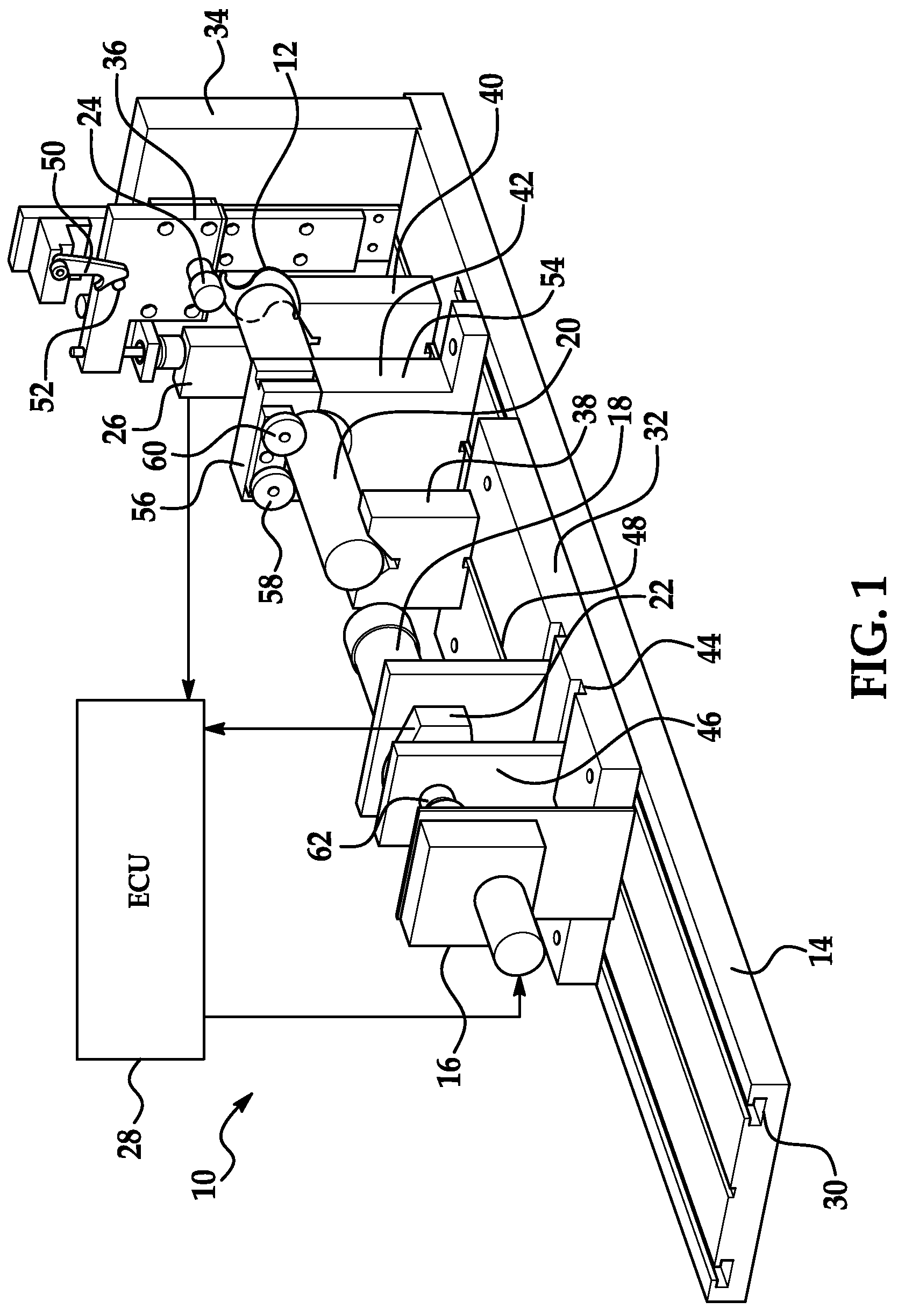
[0017]Referring now to the drawings wherein like reference numerals are used to identify identical components in the various views, FIG. 1 illustrates a system 10 for evaluating characteristics of an S-cam 12 in accordance with one embodiment of the present invention. System 10 may include a fixture base 14, a motor 16, an adapter 18, a camshaft 20, a rotary encoder 22, a cam follower 24, a linear encoder 26 and an electronic control unit 28.

[0018]Base 14 provides a means for supporting other components of system 10 and for adjusting the position of those components relative to one another. Base 14 may include a plurality of longitudinally extending grooves 30 or rails configured to permit longitudinal adjustment of the position of other components of system 10 including, for example, sub-bases 32, 34, 36, camshaft journal v-block supports 38, 40, and a camshaft retainer 42.

[0019]Sub-base 32 provides a means to support and position motor 16, adapter 18, rotary encoder 22 and support...


PUM


Abstract

A system and method for evaluating characteristics of an S-cam are provided. The inventive method includes the step of obtaining angle values and displacement values indicative of an angle of rotation of the S-cam and displacement of a cam follower caused by rotation of a lobe of the S-cam. The method further includes the step of determining a profile for the lobe of the S-cam responsive to the angle values and the displacement values. The method further includes the steps of computing a deviation of the profile from a desired profile for the lobe of the S-cam and determining a rate of change in the deviation of the profile. In addition, the system and method may evaluate characteristics such as the concentricity of the S-cam and power transfer characteristics of the S-cam.

Description

BACKGROUND OF THE INVENTION[0001]1. Field of the Invention[0002]This invention relates to a method and system for evaluating characteristics of an S-cam used in drum brakes and, in particular, to a method and system that improve the ability to measure deviation of a profile of the cam from a desired profile.[0003]2. Discussion of Related Art[0004]In a conventional drum brake, a brake drum rotates with a wheel or wheels proximate one end of an axle. The brake drum defines a radially inner braking surface. A brake spider is disposed about the axle and supports an anchor pin that extends axially from the spider. A pair of brake shoes are pivotally mounted on the anchor at a first end. Each brake shoe includes a roller, or cam follower, proximate a second end. A generally S-shaped cam engages the rollers in the brake shoes and rotation of the cam moves the brake shoes between positions of engagement and disengagement with the braking surface of the brake drum.[0005]Proper dimensioning o...

Claims


Application Information

Patent Timeline
Patent Type & Authority Patents(United States)
IPC IPC(8): F16D51/00G01C19/06G06F15/00F16D125/28
CPCF16D51/00F16D2125/28F16D2250/00
Inventor LYON, THOMAS E.JONES, JEFFREY L.LYON, GARRETT THEODORE
Owner BENDIKS SPAJSER FAUNDEJSHN BREJK LLK
Why Eureka
Try Eureka