Apparatus and method for generating electricity in liquefied natural gas carrier

a technology of liquefied natural gas and apparatus, which is applied in the direction of energy input, non-pressure vessel, container discharging from pressure vessel, etc., can solve the problems of limited hydrogen storage in hydrogen tanks, low propulsion efficiency of steam turbine propulsion systems, and limitation of the use of electricity generated by fuel cells inside the vessel

Inactive Publication Date: 2014-05-20
DAEWOO SHIPBUILDING & MARINE ENG CO LTD
View PDF15 Cites 4 Cited by
  • Summary
  • Abstract
  • Description
  • Claims
  • Application Information

AI Technical Summary

Benefits of technology

[0041]According to the embodiments of the present invention, the boil-off gas occurring in the LNG carrier may be reformed to produce fuel for the fuel cell, and the fuel produced in such a manner may be continuously supplied to the fuel cell. Therefore, the fuel cell may be adopted as a system for producing electricity required by a large vessel such as an LNG carrier, which sails a long distance.

Problems solved by technology

The steam turbine propulsion system has low propulsion efficiency.
However, since such a hydrogen tank has a limited size, the amount of hydrogen stored in the hydrogen tank may be limited.
Therefore, since the vessel including the conventional fuel cell has a limitation in supplying fuel-cell fuel, only fuel cells having a small capacity have been inevitably used as the conventional fuel cell, and the conventional fuel cell has been applied only to small vessels which sail a short distance.
Furthermore, since the electricity generation capacity of the fuel cell is small, there is a limitation in using electricity generated by the fuel cell for electricity facilities inside the vessel.
In particular, when the vessel having the conventional fuel cell operates a propulsion electromotor by using only the electricity generated from the fuel cell without including a separate generation engine, electromotors having a small output are inevitably used as the propulsion electromotor, because the electricity generation capacity of the fuel cell is small.
Accordingly, since the speed of the vessel does not only decrease, but also most power is consumed by the propulsion electromotor, there is a larger limitation in using the electricity generated by the fuel cell for the electricity facilities inside the vessel.

Method used


Image

  • Apparatus and method for generating electricity in liquefied natural gas carrier
  • Apparatus and method for generating electricity in liquefied natural gas carrier
  • Apparatus and method for generating electricity in liquefied natural gas carrier

Examples


Embodiment Construction

[0051]Exemplary embodiments of the present invention will be described below in more detail with reference to the accompanying drawings. The present invention may, however, be embodied in different forms and should not be constructed as limited to the embodiments set forth herein. Rather, these embodiments are provided so that this disclosure will be thorough and complete, and will fully convey the scope of the present invention to those skilled in the art. Throughout the disclosure, like reference numerals refer to like parts throughout the various figures and embodiments of the present invention.

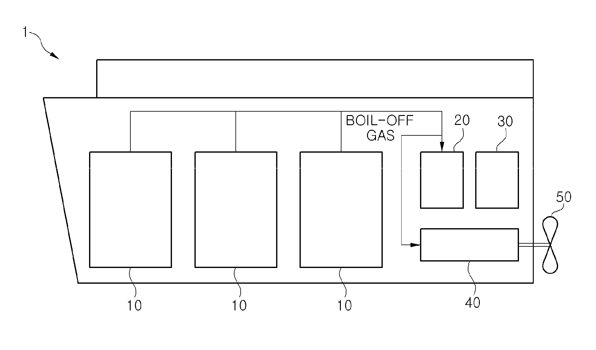
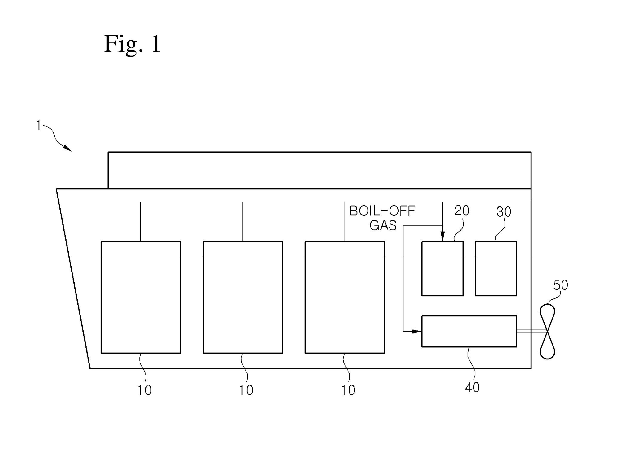
[0052]FIG. 1 is a schematic view of an LNG carrier according to an embodiment of the present invention. The LNG carrier 1 of FIG. 1 includes an LNG storage tank 10, a fuel cell module 20, a diesel storage tank 30, a propulsion system 40, and a propeller 50.

[0053]The LNG storage tank 10 stores LNG which is obtained by liquefying natural gas to ultra low temperature. Since the liquefaction t...


PUM


Abstract

Provided is an apparatus for generating electricity required by an LNG carrier which stores LNG, which is obtained by liquefying natural gas to ultra low temperature in a gas field, in an LNG storage tank and carries the stored LNG. The apparatus includes: a reformer reforming boil-off gas occurring in the LNG storage tank and producing synthetic gas; and a fuel cell generating electricity through an electrochemical reaction of the synthetic gas produced by the reformer.

Description

TECHNICAL FIELD[0001]The present invention relates to an apparatus and method for generating electricity in a liquefied natural gas (LNG) carrier, and more particularly, to an apparatus and method for generating electricity required in an LNG carrier which stores LNG, which is obtained by liquefying natural gas to ultra low temperature in a gas field, in an LNG storage tank and carries the stored LNG.BACKGROUND ART[0002]In general, an LNG carrier is a vessel which stores LNG, which is obtained by liquefying natural gas to an ultra-low temperature in a gas field is stored, in an LNG storage tank and carries the stored LNG.[0003]Examples of a propulsion system of the LNG carrier may include a steam turbine propulsion system using steam, a diesel engine propulsion system having a diesel engine for propulsion, and a dual fuel electricity propulsion system having a dual fuel engine, a generator, and a propulsion electromotor. The steam turbine propulsion system has low propulsion efficie...

Claims


Application Information

Patent Timeline
Patent Type & Authority Patents(United States)
IPC IPC(8): B63H21/17
CPCB63B25/14Y02B90/16C01B2203/066C01B3/34Y02E60/50Y02T70/5236B63J3/04H01M16/003H01M2250/20H01M2008/1293C01B2203/1241H01M8/0668C01B2203/0205H01M2250/405Y02T70/5209Y02T90/38Y02B90/12Y02T70/5263H01M8/0618Y02T70/5218B63H21/17H01M2250/402Y02T70/5281H01M2008/1095Y02E60/563Y02E60/525B63J2099/003C01B2203/1288Y02E60/526H01M2250/407Y02T90/32H01M2008/147H01M8/0662B63H2021/003Y02T90/46Y02B90/10Y02T70/50Y02T90/40Y02P20/129Y02P70/50
Inventor KWON, HYUKLEE, EUN BAEKIM, HYUN JINCHOI, JUNG HOCHOI, YONG SEOKLEE, SUNG GEUNKIM, BYUNG SUNGKIM, KI SEOK
Owner DAEWOO SHIPBUILDING & MARINE ENG CO LTD
Why Eureka
Try Eureka