Interferometric measurement of displacement in axial direction of a grating
a technology of displacement measurement and axial direction, which is applied in the direction of measurement devices, instruments, and optical conversion of sensor output, etc., can solve the problems of difficult to reduce the size and inability to achieve accurate measurement, and achieve the effect of simple configuration, reduced size, and adjustment of optical resolution
- Summary
- Abstract
- Description
- Claims
- Application Information
AI Technical Summary
Benefits of technology
Problems solved by technology
Method used
Image
Examples
embodiment 1
[0045]Basic Configuration
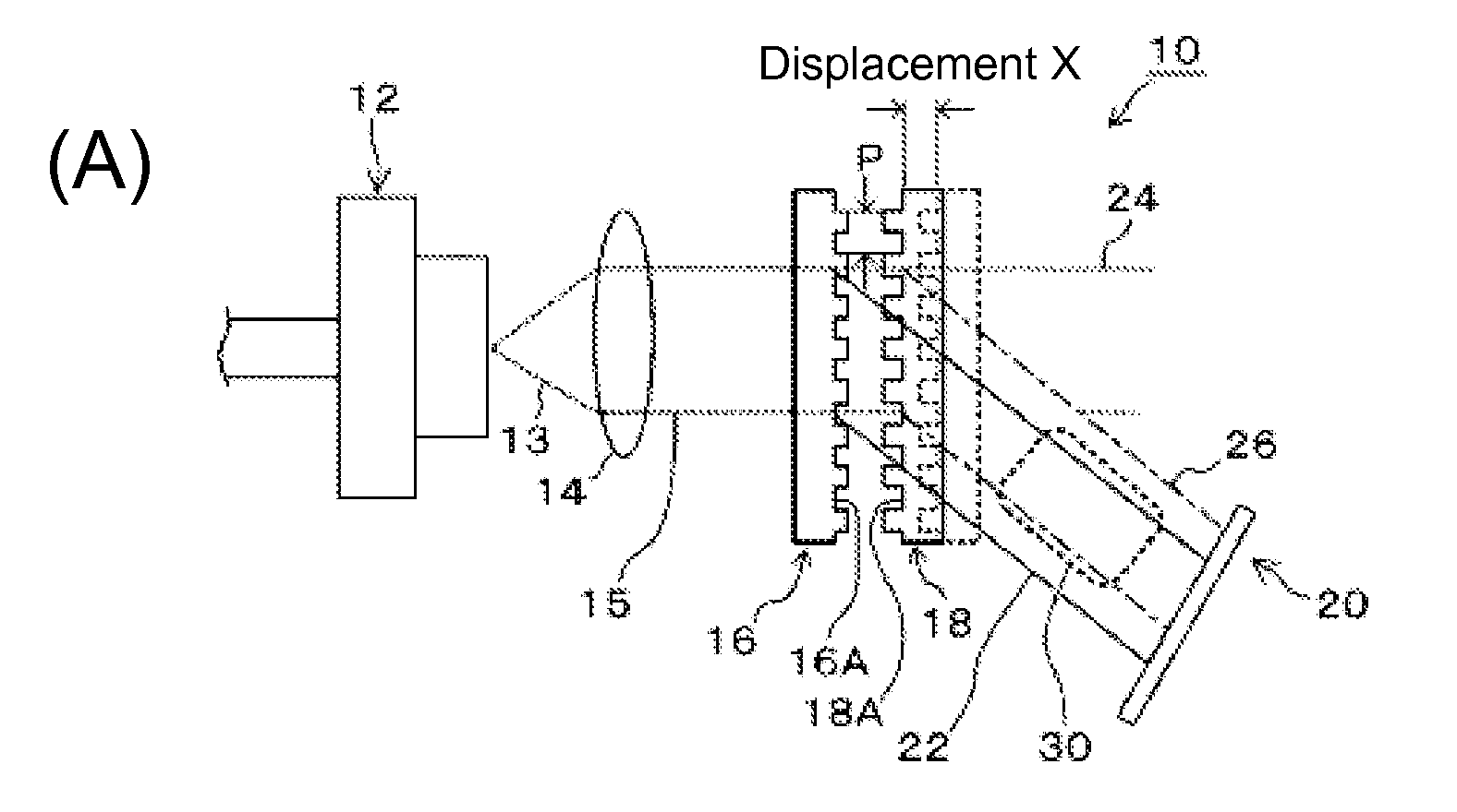
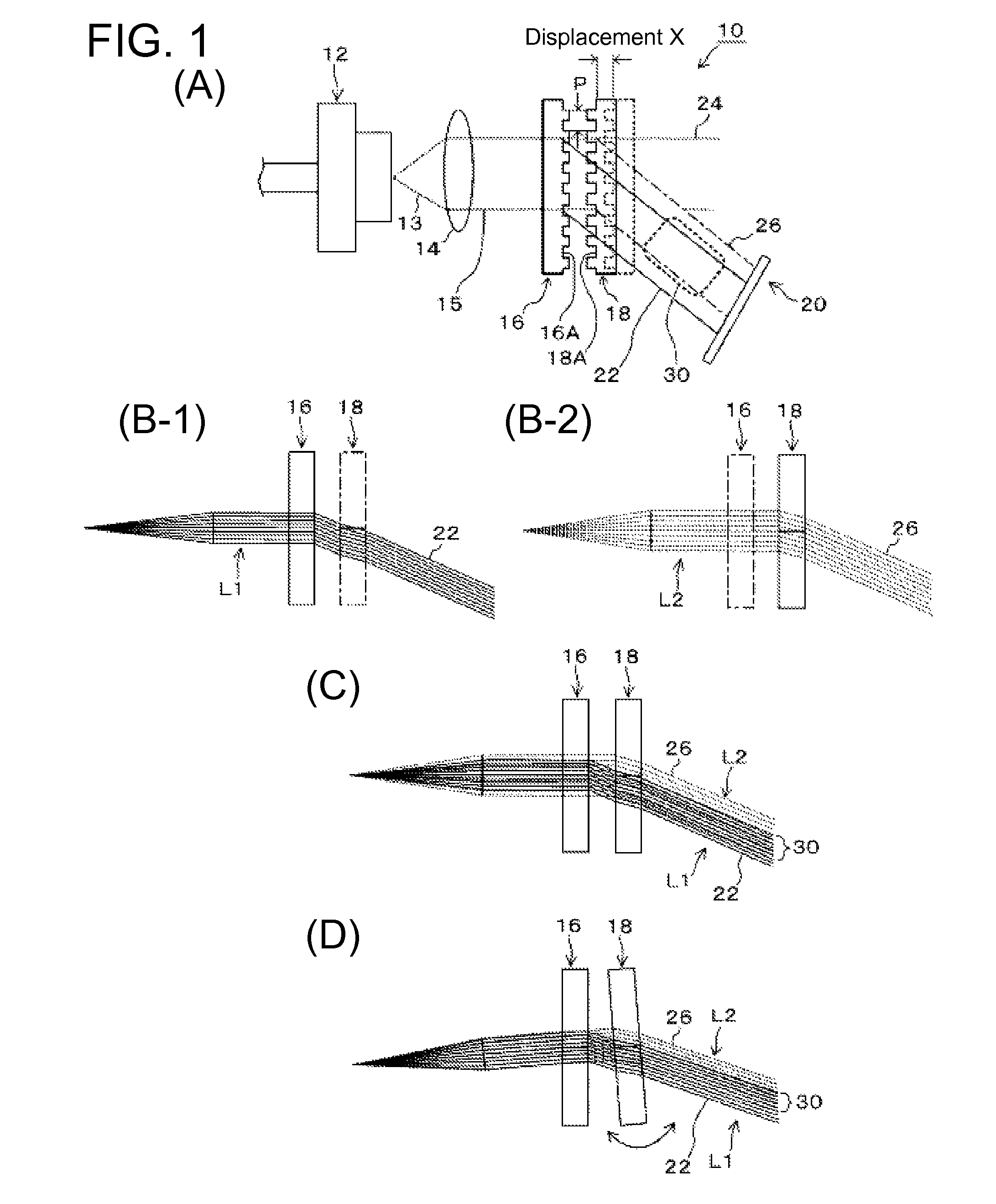
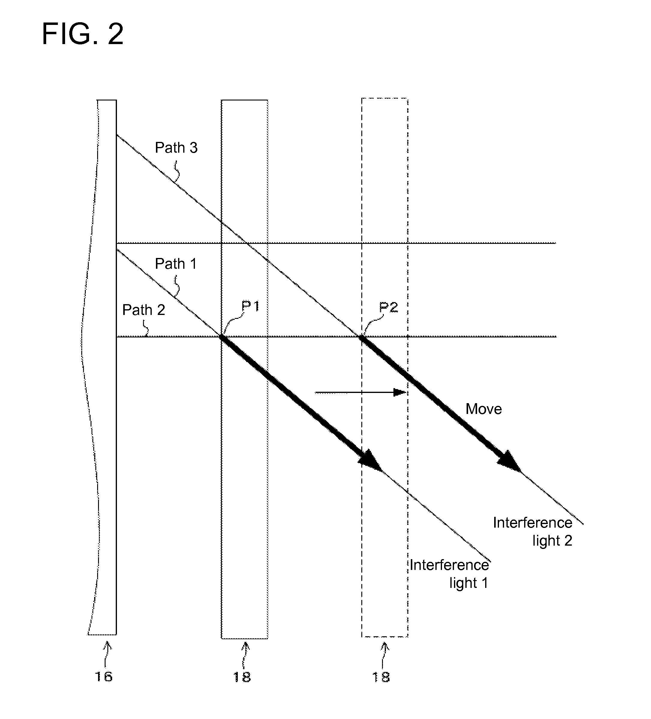
[0046]First, a basic configuration of the present invention will be explained with reference to FIG. 1. FIG. 1(A) is a diagram showing a basic configuration of this embodiment. FIGS. 1(B-1) and 1(B-2) are diagrams that respectively show an optical path 1 and an optical path 2. FIGS. 1(C) and 1(D) are diagrams showing interference between the optical paths 1 and 2. As shown in FIG. 1(A), a displacement measurement device 10 of this embodiment includes: a laser light source 12 such as a laser diode; a collimator lens 14 that turns a laser beam 13 from the laser light source 12 into parallel light 15 that travels straight; a first diffraction grating 16 on a stationary side; a second diffraction grating 18 on a moveable side that is disposed to so as to face and move relative to the first diffraction grating 16; and a first optical sensor 20 such as a photodiode. The parallel light 15 is divided into direct light 24 and diffracted light 22 when it passes throug...
application example
[0063]Next, an application example where the displacement measurement device 10 of this embodiment is used to measure a stretched amount of a brake wire of an electric assist bicycle will be explained with reference to FIGS. 4 to 8. FIG. 4 is a diagram showing an overall configuration of an electric assist bicycle. FIG. 5 is a diagram schematically showing a brake mechanism of the electric assist bicycle. FIG. 6 is a diagram showing a configuration example of a displacement measurement unit that is provided in the electric assist bicycle. FIG. 7(A) is a diagram showing a circuit configuration of a laser light source. FIG. 7(B) is a diagram showing a configuration of an optical detection circuit. FIG. 7(C) is a diagram showing a signal waveform of an output 1 from the optical detection circuit. FIG. 7(D) is a diagram showing measured characteristics of the displacement measurement unit of the displacement measurement unit. FIG. 8 shows relationships of a brake lever operation amount ...
embodiment 2
[0077]Next, Embodiment 2 of the present invention will be explained with reference to FIGS. 9 and 10. The same reference characters will be given to constituting elements that are the same as or corresponding to those in Embodiment 1 above (the same applies to other Embodiments that follow). FIG. 9(A) is a diagram showing a basic configuration of a displacement measurement device of this embodiment. FIG. 9(B) is a diagram showing a configuration of an optical detection circuit. FIG. 9(C) is a diagram showing a modification example of this embodiment. FIGS. 10(A) and 10(B) are diagrams showing signal waveforms of outputs A and B from the optical detection circuit. FIG. 10(C) is a signal waveform that indicates calculation results of the outputs A and B. This embodiment is an example of detecting phase difference by providing two optical areas with a phase difference. First, FIGS. 9(A) and 9(B) show an example of a case in which a step is provided to a diffraction grating on the movea...
PUM
 Abstract
Description
Claims
Application Information
 - R&D
- Intellectual Property
- Life Sciences
- Materials
- Tech Scout
- Unparalleled Data Quality
- Higher Quality Content
- 60% Fewer Hallucinations
Browse by: Latest US Patents, China's latest patents, Technical Efficacy Thesaurus, Application Domain, Technology Topic, Popular Technical Reports.
© 2025 PatSnap. All rights reserved.Legal|Privacy policy|Modern Slavery Act Transparency Statement|Sitemap|About US| Contact US: help@patsnap.com


