Motion space presentation device and motion space presentation method

a technology of motion space and presentation device, which is applied in the direction of image enhancement, programme control, instruments, etc., can solve the problems of inability to present the height information of the dangerous area, the inability to determine the height of the space to be occupied by the arm robot, and the inability to show the movement robot shown. to achieve the effect of reducing computational processing

Active Publication Date: 2014-05-20
PANASONIC CORP
View PDF33 Cites 23 Cited by
  • Summary
  • Abstract
  • Description
  • Claims
  • Application Information

AI Technical Summary

Benefits of technology

[0021]Thus, the motion space presentation device generates a three-dimensional region as the motion space of a movable robot using the segment approximation model thereof. Consequently, the motion space presentation device can reduce computational processing.
[0023]Thus, the motion space presentation device can express a more easily-recognized image according to the smoothness of or the distance from the three-dimensional region.
[0031]Thus, the expression form of the motion space is changed according to the moving speed. For example, the motion space presentation device can express that a portion in the motion space with a higher speed is more dangerous.
[0039]Thus, the motion space presentation device can express the proximity to the motion space. Also, the motion space presentation device can express that a dangerous area is in the proximity by lowering the transparency of the workspace.
[0041]Thus, the motion space presentation device can previously generate a three-dimensional region based on a motion planning, which is the motion space of the movable robot. Consequently, the motion space presentation device can reduce computational processing in the superimposition.
[0047]Thus, the motion space presentation device can obtain the motion planning of a movable robot without using communication means such as a network.

Problems solved by technology

However, the movable robot shown in Patent Reference 1 cannot present height information of the dangerous area.
For example, in the case of an arm robot, it is difficult to determine the height of the space to be occupied by the arm robot only by projecting the space on the installation surface of the arm robot.
Furthermore, in the case where the installation surface on which the image is projected by the projector is curved, the projected image may be deformed so that the motion space may be erroneously determined.
Consequently, it is difficult for a worker to intuitively determine the entire motion space of the arm robot by observing the image projected on the installation surface.

Method used


Image

  • Motion space presentation device and motion space presentation method
  • Motion space presentation device and motion space presentation method
  • Motion space presentation device and motion space presentation method

Examples


embodiment 1

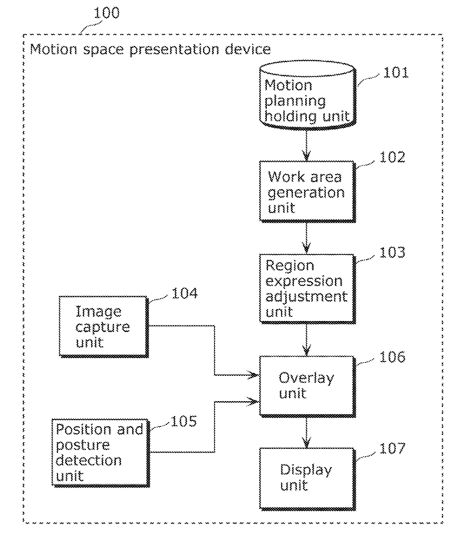
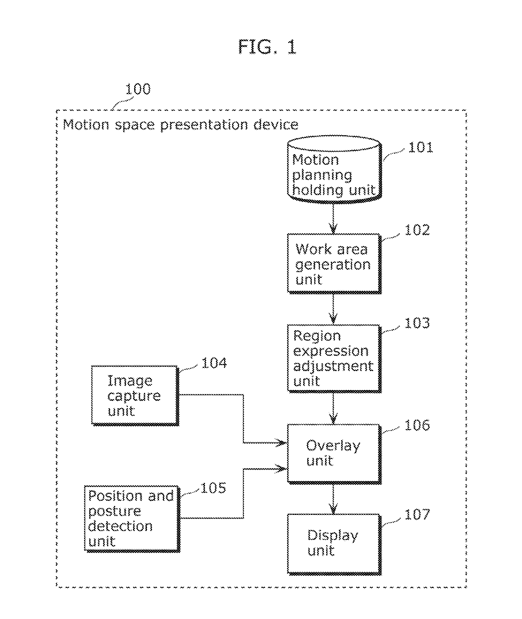
[0083]FIG. 1 is a functional block diagram of a motion space presentation device in Embodiment 1.

[0084]A motion planning holding unit 101 of FIG. 1 holds the motion planning of movable robots such as an arm robot. A work area generation unit 102 generates a three-dimensional region, as the motion space of a movable robot, from a motion planning held by the motion planning holding unit 101. A region expression adjustment unit 103 deforms the generated three-dimensional region or processes the texture of two-dimensional planes constituting the three-dimensional region so that it can be easily recognized.

[0085]An image capture unit 104 captures a real world image. A position and posture detection unit 105 detects a position and a posture of the image capture unit 104 in the real world. An overlay unit 106 extracts a partial region from the three-dimensional region outputted by the region expression adjustment unit 103, the partial region to be occupied by the movable robot after the cu...

embodiment 2

[0126]An Embodiment 2 is now described. Description of the same components as in Embodiment 1 is omitted. A motion space presentation device in Embodiment 2 also includes the same components as those of the motion space presentation device 100 in Embodiment 1 shown in FIG. 1.

[0127]FIG. 12 shows an example of an operation of a region expression adjustment unit in Embodiment 2. In Embodiment 2, a region expression adjustment unit 103 changes the color for showing a three-dimensional region.

[0128]First, the region expression adjustment unit 103 makes, as a base, a copy of the internal format of a two-dimensional plane 1201 constituting the three-dimensional region. Next, the region expression adjustment unit 103 changes an internal format 1202 of the three-dimensional region by setting the color of the two-dimensional plane as the base to red, and by setting the color of the copied two-dimensional plane to yellow. Thus, the motion space presentation device 100 can express the motion sp...

embodiment 3

[0132]An Embodiment 3 is now described. Description of the same components as in Embodiment 1 is omitted. A motion space presentation device in Embodiment 3 also includes the same components as those of the motion space presentation device 100 in Embodiment 1 shown in FIG. 1. In Embodiment 3, the movable robot 202 operates according to a plurality of operation modes defined by a motion planning. The motion space presentation device 100 changes the expression form of the motion space with a operation mode.

[0133]FIG. 14 shows an example of a motion planning of a motion planning holding unit 101 in Embodiment 3. A region expression adjustment unit 103 changes the color of a three-dimensional region by switching between the operation modes of the movable robot 202. In Embodiment 3, the movable robot 202 has two operation modes, and operates in an operation mode 1 and then operates in an operation mode 2.

[0134]FIG. 15 shows an example of an operation of the region expression adjustment u...


PUM


Abstract

A motion space presentation device includes: a work area generation unit configured to generate a three-dimensional region in which the movable robot operates; an image capture unit configured to capture a real image; a position and posture detection unit configured to detect an image capture position and an image capture direction of the image capture unit; and an overlay unit configured to selectively superimpose either an image of a segment approximation model of the movable robot as viewed in the image capture direction from the image capture position, or an image of the three-dimensional region as viewed in the image capture direction from the image capture position, on the real image captured by the image capture unit, according to the difficulty in recognizing each image.

Description

CROSS REFERENCE TO RELATED APPLICATION[0001]This is a continuation application of PCT application No. PCT / JP2010 / 007167 filed on Dec. 9, 2010, designating the United States of America.BACKGROUND OF THE INVENTION[0002](1) Field of the Invention[0003]The present invention relates to a motion space presentation device and a motion space presentation method which generate data for presenting the motion space of a movable robot which operates according to a motion planning.[0004](2) Description of the Related Art[0005]Conventional robots have a sufficient dedicated motion space into which workers are prohibited from accessing. However, in recent years, robots for performing a task while sharing space with people, such as a housekeeping robot and a double arm robot for cell production are increasing in number.[0006]When a worker works in close proximity to such a robot, the worker may come into contact with the robot and may get injured unless the worker properly perceives the motion spac...

Claims


Application Information

Patent Timeline
Patent Type & Authority Patents(United States)
IPC IPC(8): G06K9/00
CPCG06T2207/30244G05B2219/49137G05B2219/40478B25J9/1676G06T7/0018G06T7/80
Inventor MIZUTANI, KENJISATO, TAICHI
Owner PANASONIC CORP
Why Eureka
Try Eureka