Fan blade cleaning device

Inactive Publication Date: 2014-05-27
MUNCY DERRICK E
View PDF16 Cites 13 Cited by
  • Summary
  • Abstract
  • Description
  • Claims
  • Application Information

AI Technical Summary

Benefits of technology

[0021]According to another optional aspect of the invention, the device may include a variety of different cleaning elements for use in cleaning a fan blade. In one optional embodiment there may be included rolling cleaning elements wherein the cleaning elements rotate or at least have the capacity to rotate on the surfaces of the fan blade. Thus in such optional embodiments a larger surface area of the cleaning element may be in contact with the surfaces of the fan blade to promote more effective cleaning. In further optional embodiments the cleaning elements may comprise generally duster type arrangements of a variety of different fabrics synthetics cottons or the like which are known to eithe

Problems solved by technology

Often, these fans accumulate dirt, including dust and or debris as well as allergens.
Specifically, the dirt may accumulate on the upper and lower portions of the fan blades as they have a tendency to quickly gather dirt.
As dirt is generally undesirable and can include allergens, individuals generally attempt to remove the dirt from the fan blades.
Unfort

Method used


Image

  • Fan blade cleaning device
  • Fan blade cleaning device
  • Fan blade cleaning device

Examples


Embodiment Construction

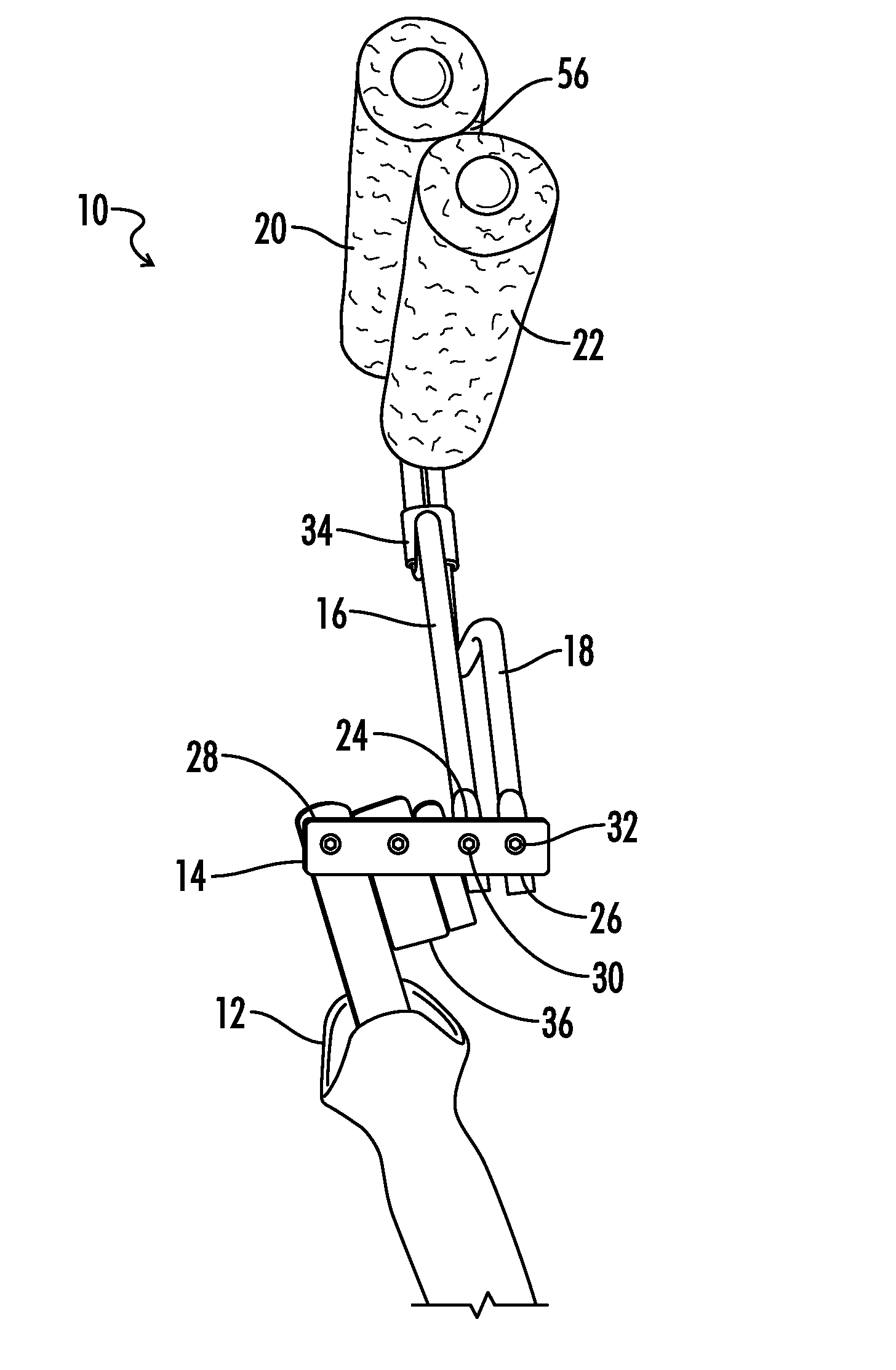
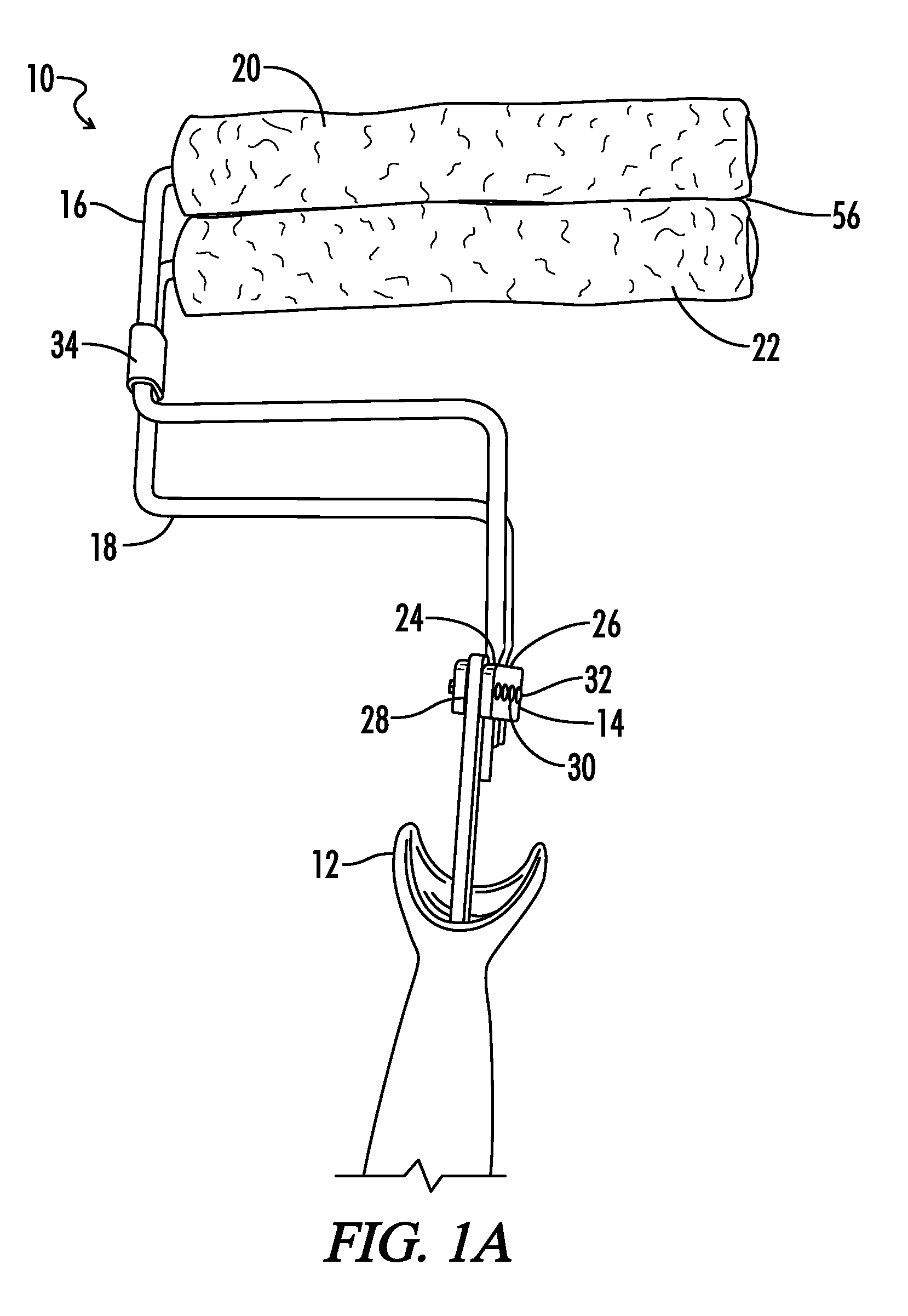
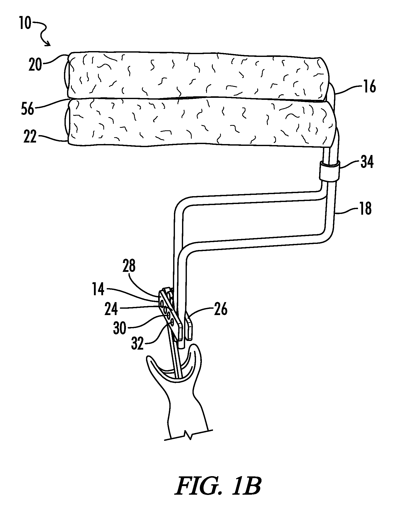
[0036]As illustrated in the accompanying drawings there are multiple optional embodiments of the cleaning device for fan blades indicated by numeral 10. Generally, cleaning device 10 includes arms 16 and 18, handle 12 and pivoting joint 14.

[0037]Handle 12 may include engagement hole 38 which may be used to connect cleaning device 10 to a pole, shaft or the like for use in cleaning fan blades that are beyond the reach of the user with the device alone. Optional embodiments of handle 12 may further include threading, grooves, posts or the like with engagement opening 38 or without so as to provide for opportunity to engage the shaft, pole or the like. Furthermore, handle 12 additionally connects to pivoting joint 14.

[0038]Pivoting joint 14 is understood to connect to both handle 12 via handle connection 28 and also connect to upper arm 16 and lower arm 18 at first distal end 24 and second distal end 26 of the arms. As used herein the term “pivoting joint” is understood to allow at lea...


PUM


Abstract

A cleaning device for blades of a fan including a first arm with distal end and proximal end, a first cleaning element attached to the proximal end and a second arm with a distal end and proximal end, a second cleaning element attached to the proximal end as well as a pivoting joint connected to the distal end of the first arm and the distal end of the second arm the pivoting joint also having a handle connection.

Description

BACKGROUND OF THE INVENTION[0001]1. Technical Field[0002]The present invention relates to the cleaning of fan blades as well as providing a method for cleaning fan blades, generally directed toward ceiling fans. In optional embodiments of the invention, the device may be capable of cleaning both the top and bottom of a ceiling fan in a substantially simultaneous fashion. Furthermore, the optional embodiments may include cleaning elements that may be disposable or the like.[0003]2. Background Art[0004]In the field of temperature regulation, fans are often utilized on the ceilings of homes, offices or other dwellings. The fans typically rotate in such a fashion so as to either push or pull air, depending on the orientation of the blades and the direction of rotation. Often, these fans accumulate dirt, including dust and or debris as well as allergens. Specifically, the dirt may accumulate on the upper and lower portions of the fan blades as they have a tendency to quickly gather dirt....

Claims


Application Information

Patent Timeline
IPC IPC(8): B08B7/00
CPCB08B7/00A47L4/00A47L25/00
Inventor MUNCY, DERRICK, E.
Owner MUNCY DERRICK E
Why Eureka
Try Eureka