Deterministic cleave of optical fiber

a technology of optical fibers and deterministic cleaving, applied in the field of optical fibers, can solve the problems of excessive light loss, cleave to propagate, and hackle on the cleaved end, and achieve the effects of simple and reliable deployment, effective, efficient and reliable approach, and minimizing light loss

Active Publication Date: 2014-06-03
SENKO ADVANCED COMPONENTS
View PDF14 Cites 17 Cited by
  • Summary
  • Abstract
  • Description
  • Claims
  • Application Information

AI Technical Summary

Benefits of technology

[0010]The present invention provides a process that can be simply and reliably deployed to properly cleave optical fibers to obtain smooth ends, so as to minimize light loss when the fibers are subsequently coupled. The process in accordance with the present invention provides an effective, efficient and reliable approach to prepare optical fiber end faces without requiring polishing.
[0011]In accordance with one aspect of the present invention, axial tension is applied to an optical fiber that had been scored with an initial surface crack at the intended cleave location, wherein the applied axial tension is regulated to maintain the stress intensity factor for the crack to be within an acceptable level to produce a stable crack growth at a reasonable rate to cleave the fiber without requiring polishing of the end surface. More particularly, in one embodiment of the present invention, the basic approach is to score a groove into the optical fiber on its outside diameter either fully around the circumference of the fiber or in selective regions around the circumference, and then apply a time-varying force co-axial to the fiber longitudinal axis to cleave the fiber. The fiber may or may not be initially held under a substantially constant tension when it is being scored. A carefully controlled scoring process provides only an initial surface crack without sub-surface crack, which defines the location where crack propagation across the fiber will be initiated with sufficient axial tension. The score may be produced mechanically by a scoring tool, or a laser cut, or subjecting to other forms of ablation such as a focused ion beam. Applying a time varying force to the fiber causes the initial crack to propagate radially inward towards the fiber's center. In one embodiment, careful control of the applied tension force with time acts to control the velocity of the propagating crack by maintaining substantially constant stress intensity factor. In another embodiment, the applied axial tension force is reduced with time and / or crack growth (as crack propagates). As a result, the strain energy in the fiber material is released by formation of a single plane with an optical quality surface without requiring polishing. More particularly, a substantially flat optical surface or facet of enhanced optical quality is formed at the cleaved end of the optical fiber. The facet surface may be formed at an angle to the longitudinal axis of the fiber by appropriately placing the initial score.

Problems solved by technology

These devices often require the coupling of fibers in end-to-end relationship with the coupling representing a source of light loss.
If the ends of the fiber are uneven, excessive light loss can result due to reflection and refraction of light at the cleaved end surface (e.g., a splice or juncture region).
However, too much tension will cause the cleave to propagate too fast, creating hackle on the cleaved end.
If too little tension is used, the scoring edge will be required to penetrate too deeply into the fiber to initiate the cleave, giving a poor cleave.
Such polishing step can be automated, but it requires elaborate and expensive equipment and a rather complex procedure, which limit the operation to being performed in a factory or laboratory.
Furthermore, the shape of the fiber is distorted, often increasing in diameter, when the end of the fiber melts and resolidifies as a result of the laser polishing process.

Method used


Image

  • Deterministic cleave of optical fiber
  • Deterministic cleave of optical fiber
  • Deterministic cleave of optical fiber

Examples


Embodiment Construction

[0018]This invention is described below in reference to various embodiments with reference to the figures. While this invention is described in terms of the best mode for achieving this invention's objectives, it will be appreciated by those skilled in the art that variations may be accomplished in view of these teachings without deviating from the spirit or scope of the invention.

[0019]The present invention provides a process that can be simply and reliably deployed to properly cleave optical fibers to obtain smooth ends, so as to minimize light loss when the fibers are subsequently coupled (e.g., spliced or coupled end-to-end). The process in accordance with the present invention provides an effective, efficient and reliable approach to prepare optical fiber end faces without requiring polishing, which facilitates operations in a factory and could facilitate operations in field environment as well.

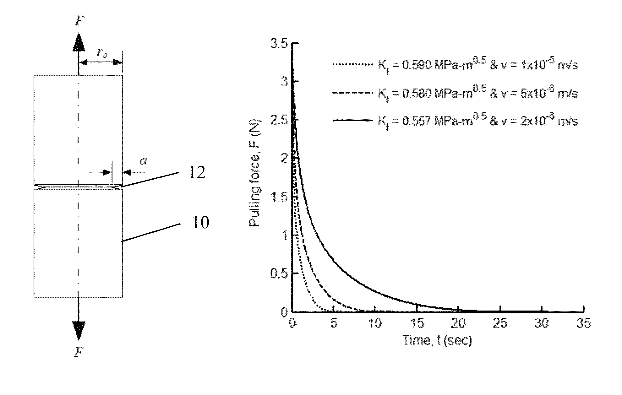
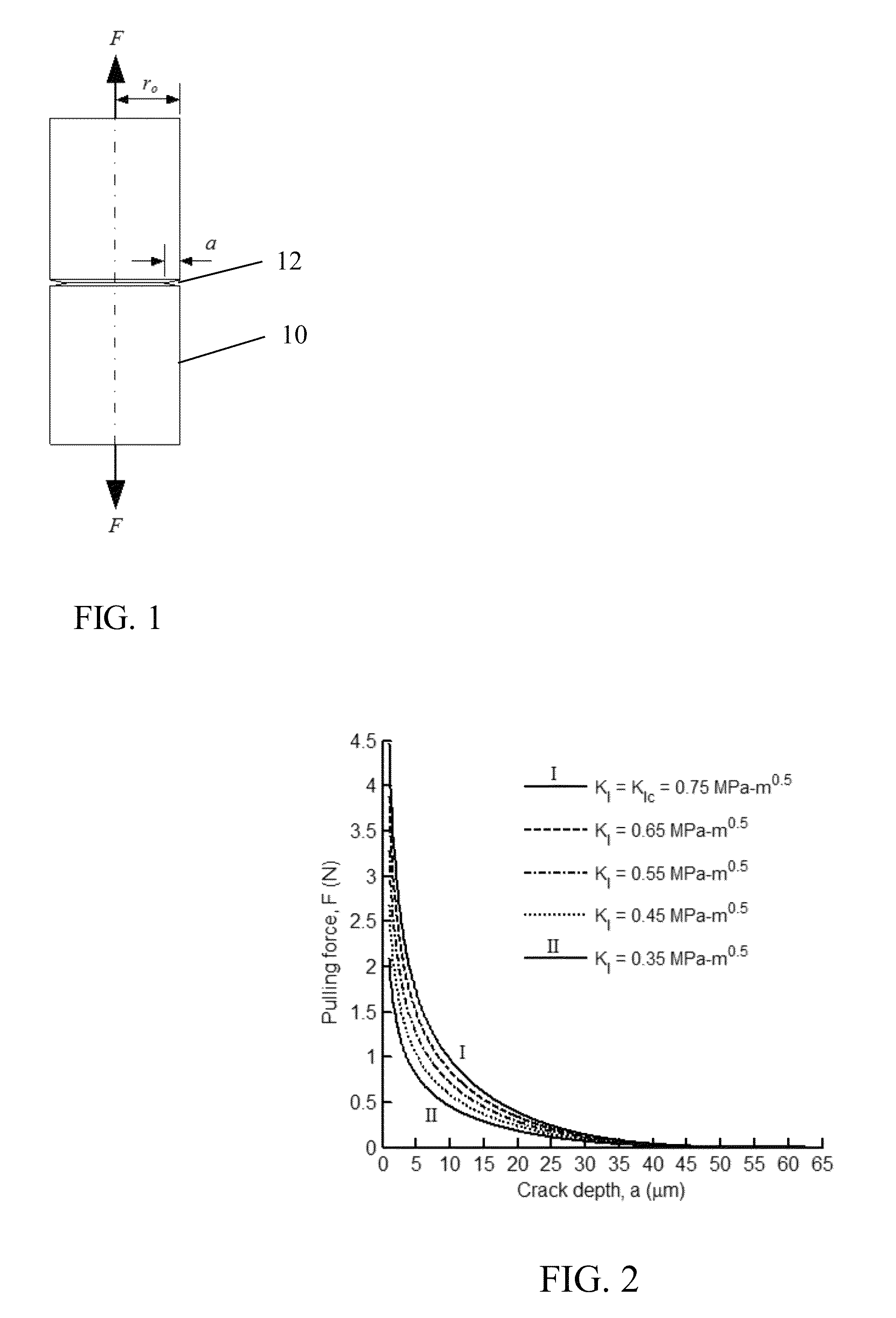
[0020]In one aspect of the present invention, axial tension applied to the optical f...


PUM


Abstract

Axial tension is applied to an optical fiber that had been scored at the intended cleave location, wherein the axial tension is applied in a time-varying manner to maintain the stress intensity factor for crack on the fiber within an acceptable level to produce a stable crack growth at a reasonable rate to cleave the fiber without requiring polishing of the end surface. Careful control of the applied tension force with time acts to control the velocity of the propagating crack by maintaining substantially constant stress intensity factor. The applied axial tension force is reduced with time and / or crack growth (as crack propagates). As a result, the strain energy in the fiber material is released by formation of a single plane with an optical quality surface without requiring polishing. A substantially flat optical surface of enhanced optical quality is formed at the cleaved end of the optical fiber.

Description

PRIORITY CLAIM[0001]This application claims the priority of U.S. Provisional Patent Application No. 61 / 359,327 filed on Jun. 28, 2010, which is fully incorporated by reference as if fully set forth herein. All publications noted below are fully incorporated by reference as if fully set forth herein.BACKGROUND OF THE INVENTION[0002]1. Field of the Invention[0003]The present invention relates to optical fibers, in particular cleaving of optical fibers to shorten their length and produce a flat end on the fiber.[0004]2. Description of Related Art[0005]There are many advantages to transmitting light energy via optical fiber waveguides and the use thereof is diverse. Single or multiple fiber waveguides may be used simply for transmitting visible light to a remote location. Complex communication systems may transmit multiple specific optical signals. These devices often require the coupling of fibers in end-to-end relationship with the coupling representing a source of light loss. The cle...

Claims


Application Information

Patent Timeline
Patent Type & Authority Patents(United States)
IPC IPC(8): B26F3/00
CPCG02B6/25Y10T225/12Y10T225/325Y10T225/321G02B6/24
Inventor BARNOSKI, MICHAEL K.GULATI, SURESH T.HII, KING-FUKECK, DONALDPOWELL, WILLIAM R.VALLANCE, R. RYAN
Owner SENKO ADVANCED COMPONENTS
Why Eureka
Try Eureka