
Method of laser polishing a connectorized optical fiber and a connectorized optical fiber formed in accordance therewith

a technology of connectorized optical fibers and laser polishing, which is applied in the field of optical fibers, can solve the problems of excessive light loss, undesirable optical effects, and rough optical surfaces, and achieve the effect of effective, efficient and reliable methods

Active Publication Date: 2018-03-13
SENKO ADVANCED COMPONENTS
View PDF38 Cites 3 Cited by
  • Summary
  • Abstract
  • Description
  • Claims
  • Application Information

AI Technical Summary

Benefits of technology

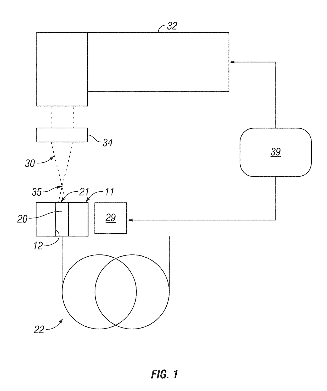
[0012]The present invention provides a novel method of forming a connectorized optical fiber cable, including a process of laser polishing the end face of a connectorized optical fiber. The laser polishing process in accordance with the present invention provides an effective, efficient and reliable approach to finishing optical fiber end faces to achieve acceptable surface geometries and surface properties (e.g., smoothness).
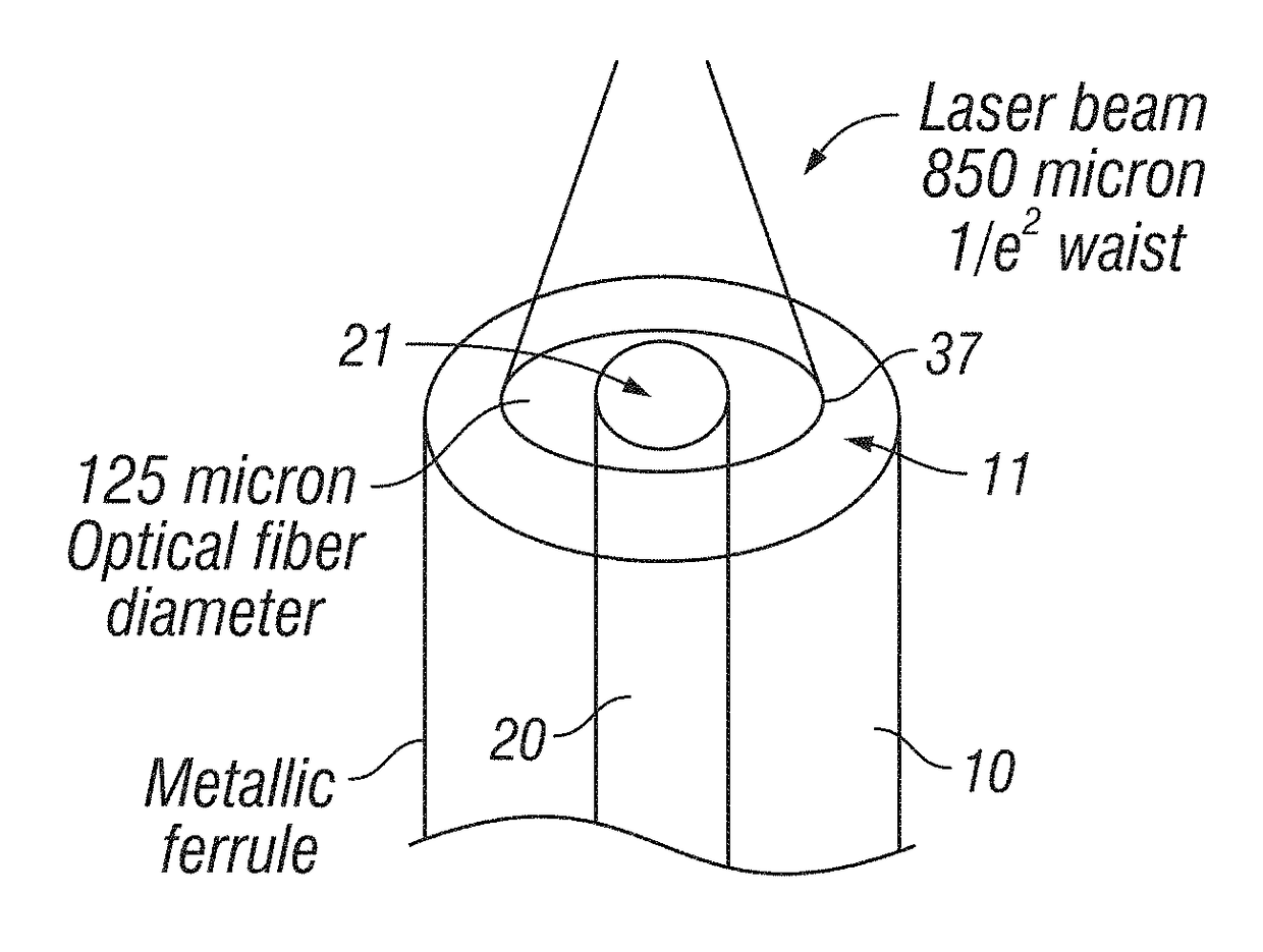
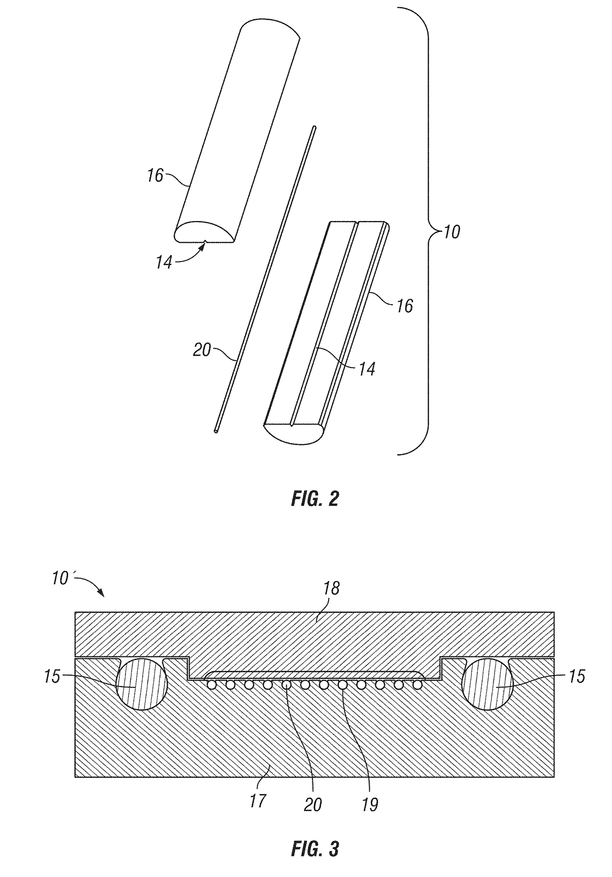
[0013]In accordance with one aspect of the present invention, laser polishing is performed on a cleaved end face of a connectorized optical fiber that has been terminated by mounting in a metal ferrule. For purpose of the present invention, a connectorized optical fiber comprising an optical fiber terminated by fixedly mounting in a metal ferrule, and the optical fiber is not demounted from such ferrule after subsequent polishing / finishing of its end face (the optical fiber and the ferrule may be assembled into a connector). The metal ferrule includes a body having a groove for receiving a bare terminating end section of the optical fiber (i.e., including core with cladding exposed, without protective buffer coating and jacket layers). In one embodiment, the ferrule is defined by a body having a bore or groove sized to securely retain the bare optical fiber. In a further embodiment, the body is defined by two ferrule halves, which may be identical (the ferrule halves each has a semi-cylindrical-shaped grove; the ferrule halves clamp the bare optical fiber), or different (e.g., one of the ferrule halve has a U-shaped groove that secured retain the bare optical fiber, and the other ferrule halve does not have a groove). No adhesive (e.g., epoxy) is applied between the bare optical fiber and the ferrule. In one embodiment, the ferrule (or ferrule halves) may be formed by precision stamping a metal blank, to accurately define the dimension and geometries of the external and internal surface features of the ferrule (or ferrule halves), so that the ferrule can accurately align the axis of the optical fiber to an external connection point (e.g., using a sleeve to optically couple to a connecting ferrule holding a connecting optical fiber).
[0014]The laser beam is directed perpendicular to the end face of the optical fiber, or generally along and / or parallel to the longitudinal axis of the optical fiber. In one embodiment, the laser beam is defocused so that the spot size is larger than the bare optical fiber diameter (e.g., a spot size several times the diameter of the bare fiber or fiber end face). Incident radiation energy is reflected by the surface of the metal ferrule. Consequently, the central portion of the Gaussian (TEM00) mode of the laser is applied to the optical fiber. This provides a more uniform spatial distribution of the radiation energy over the area of the end face of the fiber, which results in less reshaping of the end face. Therefore, no rotation of the fiber about its axis is required to maintain axial symmetry. Given the relatively large spot size of the laser beam compared to the diameter of the bare fiber end face, the laser beam does not need to be precisely aligned to the fiber end face (i.e., the optical axis of the laser beam is misaligned with center of the fiber end face).
[0015]In accordance with the present invention, the metal ferrule provides heat conduction to prevent excessive heat built up at the fiber tip, which could vaporize the material of the optical fiber and / or cause optical changes in the optical fiber (e.g., as a result of diffusion of dopants (e.g., fluorine and germanium) within the cladding and core of the fiber, and / or as a result of thermo-mechanical residual stress to avoid stress-induced birefringence in the optical fiber). The fiber tip / end face is softened or slightly melted (e.g., to about 10 microns) by the laser beam to repair typical surface defects but does not appreciably change the shape of the fiber tip / end face, since the material of the optical fiber is not vaporized or excessively softened. The metal ferrule does not absorb radiation of the laser beam, as it reflects the laser beam.
[0016]The laser polished end face of the optical fiber achieves desired surface geometries and surface properties, without requiring subsequent mechanical grinding and / or polishing. This avoids formation of a high index layer normally introduced by such mechanical processing.
[0017]In one embodiment, the connectorized optical fiber is pre-shaped (e.g., by mechanical grinding or laser shaping) prior to laser polishing. The end face of the optical fiber (and the end face of the ferrule) is pre-shaped to achieve the desired fiber undercut / protrusion (e.g., −150 nm undercut / +50 nm protrusion) with respect to the ferrule end face. As a result of such preshaping process, a slight convex surface is obtained. It has been found that the laser polishing process in accordance with the present invention could “relax” the convex surface to achieve a more desirable flatter fiber end face (i.e., the radius of curvature of the fiber end face is larger after laser polishing as compared to the radius of curvature of the fiber end face prior to laser polishing). Further, in the presence of a high index layer introduced by previous mechanical polishing at the fiber end face, it has been found that the laser polishing process in accordance with the present invention could also cause the fiber material in such layer to reduce in index of refraction, thus further reducing return losses.

Problems solved by technology

If the ends of the fiber are uneven, excessive light loss can result due to reflection and refraction of light at the cleaved end surface (e.g., a splice or juncture region).
Roughness of the optical surface presents limits in the efficiency of optical signal transmissions by both scattering light and introducing contact gaps in the mating of connectors.
Finishing of the end faces of the fibers involves a laborious procedure which entails placing a quantity of an uncured epoxy in the passage of a zirconia terminal ferrule into which the fiber is to be inserted.
While the prior art laser shaping / polishing processes may reduce high back reflections by reducing surface roughness, a high index layer is still being introduced, which are often viewed as fundamental problems.
This results in undesirable optical effects, unless this convex surface is further shaped by mechanical grinding.
Further, polishing not just bare fiber but connectorized fiber still remains an issue.
Epoxy typically absorbs the laser energy and subsequently melts, burns, or vaporizes at the high power densities required to soften or melt the fiber; this which contaminates the end face of the optical fiber and needs to be removed and it compromises the retention of the fiber within the ferrule.
Ceramic ferrules also absorb energy from the laser beam, and due to their low thermal conductivity, rapid temperature changes during the laser treatment can introduce cracking in the zirconia (ZrO2) and alumina (Al2O3) ferrules.
Further, the prior methods require precision alignment of the applied laser beam, and additional fine polishing steps after the application of the laser, which increases burden and complexity in manufacturing, and which could result in a high index layer.
The drawbacks of the prior art fiber end face polishing processes posed significant challenges to meet the stringent specifications set forth by prevailing industry standards, such as GR-326-CORE (Generic Requirements for Singlemode Optical Connectors and Jumper Assemblies, Issue 4).

Method used


Image

  • Method of laser polishing a connectorized optical fiber and a connectorized optical fiber formed in accordance therewith
  • Method of laser polishing a connectorized optical fiber and a connectorized optical fiber formed in accordance therewith
  • Method of laser polishing a connectorized optical fiber and a connectorized optical fiber formed in accordance therewith

Examples


case 1

[0048[0049]Pre-laser polish radius of curvature of fiber end face=7.88 mm[0050]Post-laser polish radius of curvature of fiber end face=8.82 mm

case 2

[0051[0052]Pre-laser polish radius of curvature of fiber end face=5.59 mm[0053]Post-laser polish radius of curvature of fiber end face=12.07 mm

[0054]Accordingly, laser polishing also can be effective to “correct” the radius of curvature of the fiber end face after it has been subject to rough polishing associated with shaping the ferrule end face, thus reducing return losses associated with the fiber end face.

[0055]Further, in the presence of a high index layer introduced by previous mechanical grinding and / or polishing at the fiber end face, it has been found that the laser polishing process in accordance with the present invention could also cause the fiber material in such layer to reduce in index of refraction, thus further reducing return losses. Thus if there is material having a high index film / layer present at the fiber end face prior to laser polishing, the index of refraction in that layer of material is decreased by the laser beam during laser polishing process. According...


PUM


Abstract

Laser polishing is achieved by directing laser beam perpendicular at the fiber end face in a connectorized optical fiber having a metal ferrule. The spot size of the laser beam is larger than the bare optical fiber diameter, providing a more uniform spatial distribution of the radiation energy over the fiber end face. The metal ferrule provides heat conduction to prevent excessive heat built up at the fiber tip, which would lead to undesirable surface defects and geometries. The connectorized optical fiber may be pre-shaped prior to laser polishing. Subsequent laser polishing flattens the fiber end face.

Description

PRIORITY CLAIM[0001]This application claims the priority of U.S. Provisional Patent Application No. 62 / 078,868 filed on Nov. 12, 2014, which is fully incorporated by reference as if fully set forth herein. All publications noted below are fully incorporated by reference as if fully set forth herein.BACKGROUND OF THE INVENTION[0002]Field of the Invention[0003]The present invention relates to optical fibers, and more particularly to the finishing of the end face of an optical fiber.[0004]Description of Related Art[0005]There are many advantages to transmitting light energy via optical fiber waveguides and the use thereof is diverse. Single or multiple fiber waveguides may be used simply for transmitting visible light to a remote location. Complex communication systems may transmit multiple specific optical signals. These devices often require the coupling of optical fibers in end-to-end relationship, to effectively place the end faces of the two optical fibers in face-to-face juxtapos...

Claims


Application Information

Patent Timeline
Patent Type & Authority Patents(United States)
IPC IPC(8): G02B6/38B23K26/00B23K103/00
CPCG02B6/3863B23K26/0075G02B6/3885G02B6/3854B23K2203/54B23K26/3576B23K2103/54
Inventor WOODWARD, RYAN H.CHEN, YANGVALLANCE, ROBERT RYANJAQUAY, ERIC
Owner SENKO ADVANCED COMPONENTS
Learn More