

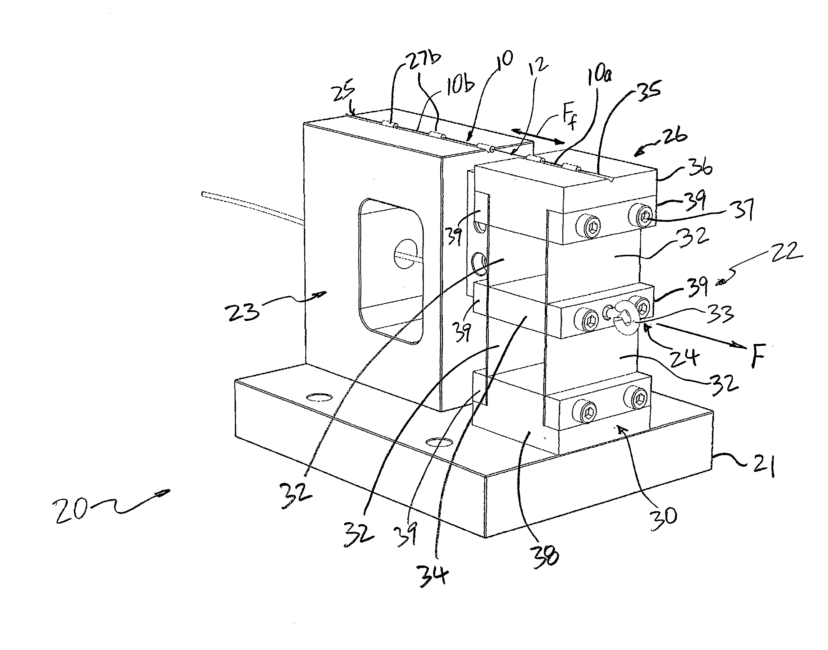
Tensioning device having a flexure mechanism for applying axial tension to cleave an optical fiber
- Summary
- Abstract
- Description
- Claims
- Application Information
AI Technical Summary
Benefits of technology
Problems solved by technology
Method used
Image

Examples
Embodiment Construction
[0027]This invention is described below in reference to various embodiments with reference to the figures. While this invention is described in terms of the best mode for achieving this invention's objectives, it will be appreciated by those skilled in the art that variations may be accomplished in view of these teachings without deviating from the spirit or scope of the invention.
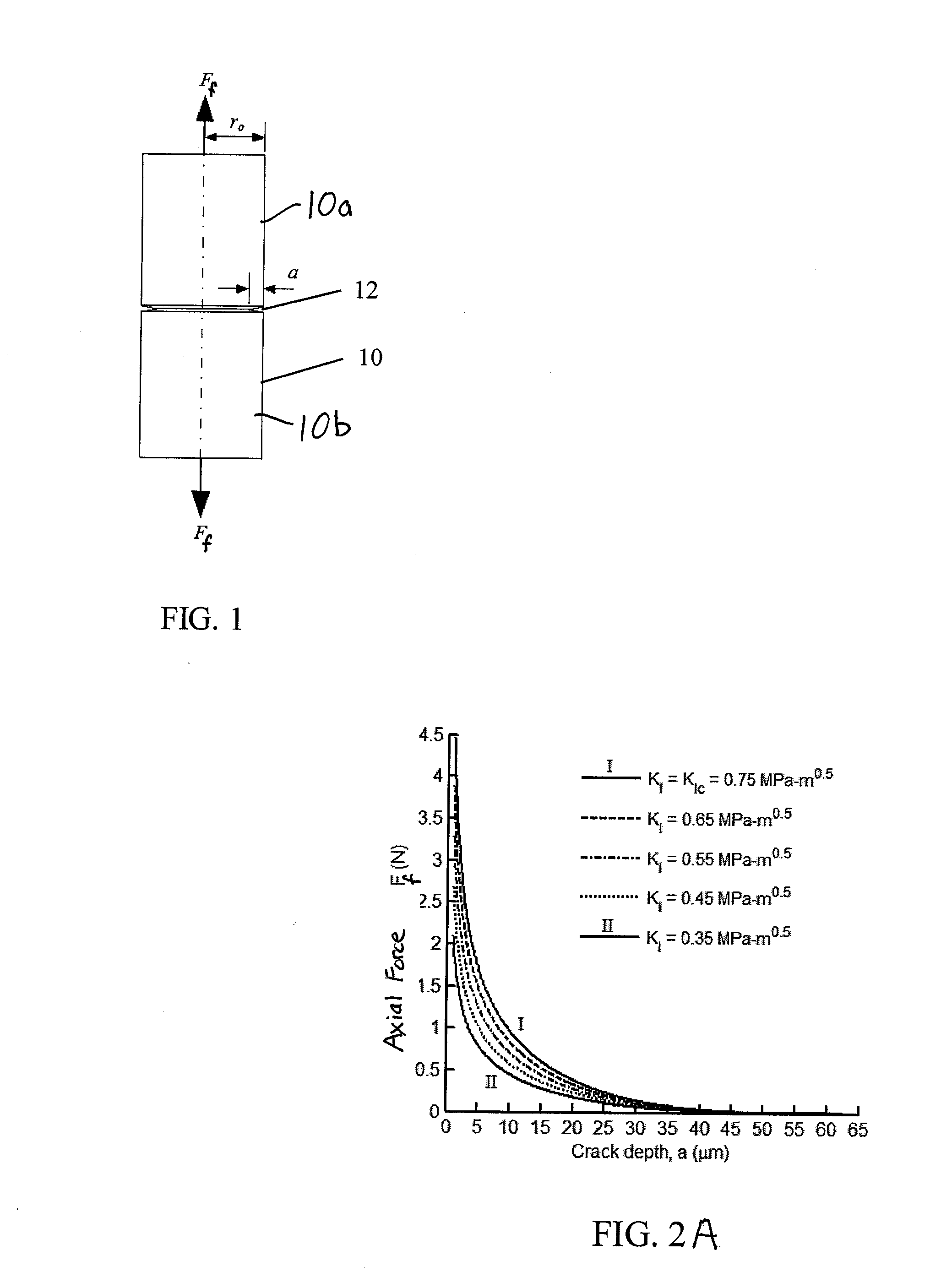
[0028]The present invention provides a mechanism in a device to apply axial tension in a controlled manner, which provides the necessary axial tension to properly cleave optical fibers to obtain smooth damage-free ends, so as to minimize light loss when the fibers are subsequently coupled. The cleaving mechanism in accordance with the present invention provides an effective, efficient and reliable approach to prepare optical fiber end faces that are flat, which may obviate subsequent polishing.
[0029]By way of background, there are three basic modes of fracture of fiber: Mode I (opening mode), Mode II (slid...
PUM
| Property | Measurement | Unit |
|---|---|---|
| Force | aaaaa | aaaaa |
| Flexibility | aaaaa | aaaaa |
| Stress intensity factor | aaaaa | aaaaa |
Abstract
Description
Claims
Application Information