A Time Grating Linear Displacement Sensor Based on Alternating Electric Field

A technology of linear displacement and alternating electric field, which is applied in the direction of instruments, electric devices, and electromagnetic means, can solve the problems of high power consumption, heavy sensor quality, and low production efficiency of time grating linear displacement sensors, and achieve light weight, The effect of high resolution and low cost

Active Publication Date: 2011-12-21
通用技术集团国测时栅科技有限公司
View PDF2 Cites 39 Cited by
  • Summary
  • Abstract
  • Description
  • Claims
  • Application Information

AI Technical Summary

Problems solved by technology

In order to achieve high-precision measurement, the stator coil and induction coil substrate of this time grating linear displacement sensor require the use of magnetically permeable materials, resulting in heavy sensor quality; the production process requires winding, and the produ

Method used


Image

  • A Time Grating Linear Displacement Sensor Based on Alternating Electric Field
  • A Time Grating Linear Displacement Sensor Based on Alternating Electric Field
  • A Time Grating Linear Displacement Sensor Based on Alternating Electric Field

Examples


Embodiment Construction

[0023] The present invention will be further described below in conjunction with accompanying drawing.

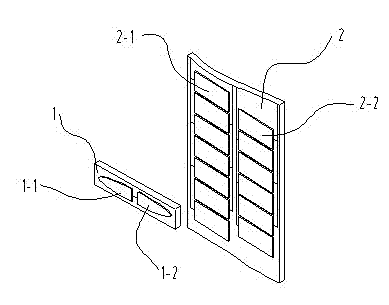
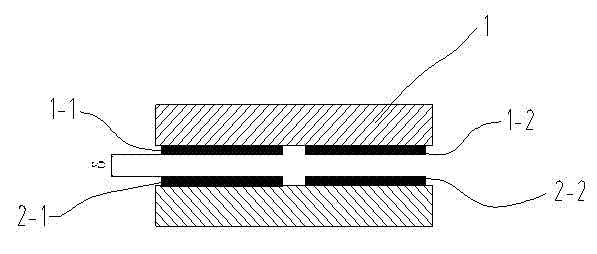
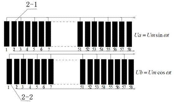
[0024] Such as Figure 1(a) , Figure 1(b) , figure 2 , Figure 4(a) , Figure 4(b) As shown, the sensor of the present invention includes two parts: a probe base 1 and a scale base 2; quartz is used as the base material, and a layer of iron-nickel alloy is sprayed on the surface of the quartz as an electrode. The upper surface of the fixed-length substrate 2 is evenly covered with left and right rows of rectangular electrodes of the same size, that is, the fixed-length left row of electrodes 2-1 and the fixed-length right row of electrodes 2-2, and the size of each electrode is 10mm*4.9 mm, the spacing between each row of adjacent electrodes is 0.1mm. The number of fixed-length electrodes 2-1 in the left row is equal to the number of fixed-length electrodes 2-2 in the right row, and the starting positions differ by 2.5mm. The lower surface of the probe base 1 is cov...


PUM


Abstract

A time grating linear displacement sensor based on an alternating electric field comprises two parts, namely a head measuring base body and a sizing base body, wherein a left electrode and a right electrode are coated on the lower surface of the head measuring base body; a left row of electrodes and a right row of electrodes are coated on the upper surface of the sizing base body; the distance between the start position of the left row of electrodes and the start position of the right row of electrodes of the sizing base body is 1/2 electrode width; the lower surface of the head measuring base body is relatively parallel to the upper surface of the sizing base body; a fixed clearance theta is formed between the lower surface of the head measuring base body and the upper surface of the sizing base body; a left group of differential capacitors and a right group of differential capacitors are formed; the head measuring base body and the sizing base body are relatively moved; the left rowof electrodes and the right row of electrodes of the sizing base body are respectively connected with sinusoidal excitation voltages with equal amplitude and equal frequency, wherein the difference between the phases of the sinusoidal excitation voltages is 90 degrees; two routes of electric field coupling signals respectively generated by the left electrode and the right electrode of the head measuring base body are combined into one route of travelling wave signals Uo through an adding circuit; after the route of travelling wave signals Uo is shaped with one route of common-frequency reference signals Ur with fixed phase, phase comparison is performed; and the phase difference between the two routes of signals is represented by an interpolated clock pulse and is transformed to generate a linear displacement value. The time grating linear displacement sensor based on the alternating electric field has the advantages of low power consumption, light weight, high resolution and low cost.

Description

technical field [0001] The invention belongs to a precision linear displacement measuring sensor. technical background [0002] In the field of precision linear displacement measurement, grating sensors such as gratings, magnetic gratings, and capacitive gratings are mainly used. The measurement standard uses periodic grating lines that are evenly divided in space, and the displacement is obtained by counting the grating lines. Precision measurement requires the ability to measure the linear displacement of 1mm~0.1mm. In order to meet the measurement accuracy and resolution requirements, it cannot be achieved by the precision engraved line itself. It is necessary to use high-precision electronic subdivision technology, so that the manufacture of these grid sensors The process is demanding, the cost is high, and the anti-interference ability is poor. [0003] In recent years, a kind of time grating sensor with clock pulse as the reference of displacement measurement has been...

Claims


Application Information

Patent Timeline
IPC IPC(8): G01B7/02
Inventor 刘小康彭东林王先全朱革彭凯
Owner 通用技术集团国测时栅科技有限公司
Why Eureka
Try Eureka