
Refrigerating apparatus and method of controlling the same

a technology of refrigerating apparatus and control method, which is applied in the field of refrigerating apparatus, can solve the problems of reducing the quality of stored articles, destroying the cells of stored articles, and losing a large amount of nutritional value, so as to improve the freezing quality of stored articles

Inactive Publication Date: 2014-06-10
SAMSUNG ELECTRONICS CO LTD
View PDF11 Cites 0 Cited by
  • Summary
  • Abstract
  • Description
  • Claims
  • Application Information

AI Technical Summary

Benefits of technology

The refrigerating apparatus and method described in this patent improve the quality of stored food by controlling the temperature. By reducing the amount of cold air supplied to the storage area after the freezing process is complete, the temperature is maintained at a level that helps to prevent the food from becoming too damaged.

Problems solved by technology

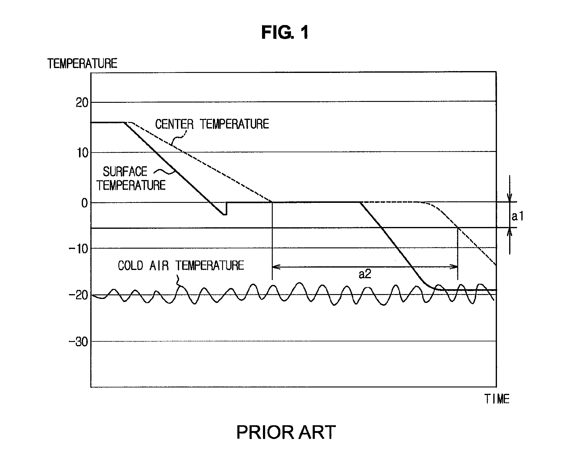
Thereby, the stored article remains in a maximum ice crystal formation zone a1 for a long time a2, and thus large ice crystals or needle-shaped ice crystals are generated and the generated ice crystals destroy the cells of the stored article and lower the quality of the stored article.
Accordingly, the stored article, such as animal and bird meat or fish, contains many drips after thawing, and loses much of its nutritional value, thus becoming unpleasant to taste.
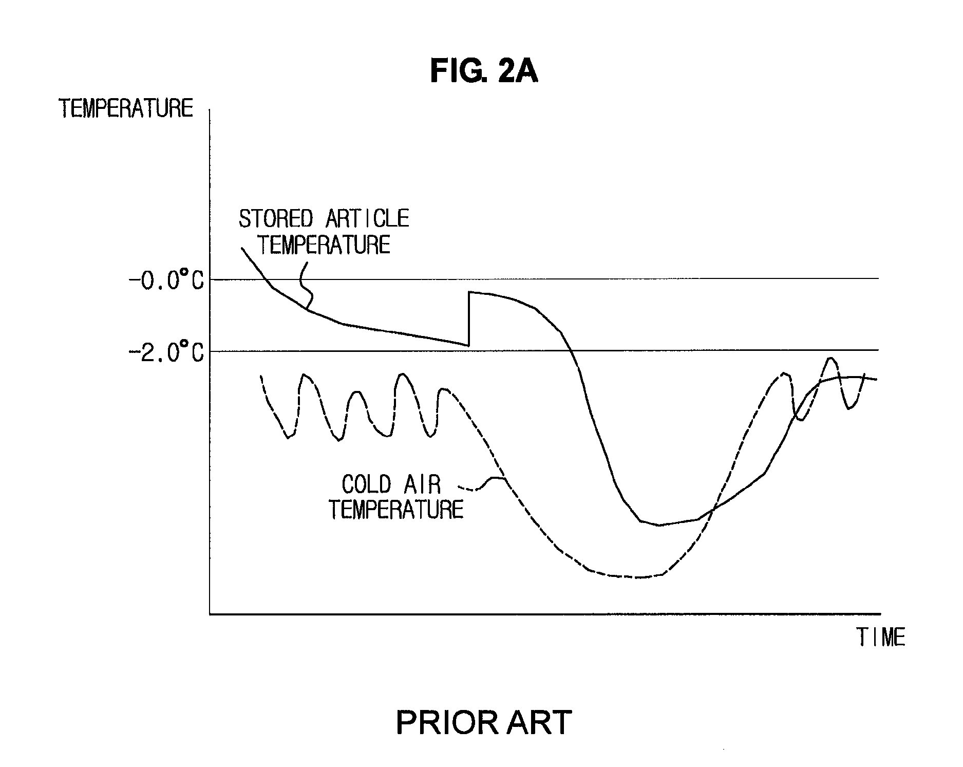
Since when the article is super-cooled, super-cooling may be terminated before the article reaches a designated temperature for the designated time b2, maintenance of the super-cooling of the article is difficult.
Further, when the super-cooling of the article is terminated, the article remains in a maximum ice crystal formation zone b1 for a long time, and large ice crystals are formed in the article during this time, thus lowering the quality of the article.

Method used


Image

  • Refrigerating apparatus and method of controlling the same
  • Refrigerating apparatus and method of controlling the same
  • Refrigerating apparatus and method of controlling the same

Examples


Embodiment Construction

[0042]Reference will now be made in detail to the embodiment, examples of which are illustrated in the accompanying drawings, wherein like reference numerals refer to like elements throughout.

[0043]FIG. 3 is an exemplary view of a refrigerating apparatus in accordance with one embodiment. As the refrigerating apparatus in accordance with this embodiment, a freezing chamber of a refrigerator will be exemplarily described.

[0044]The refrigerator includes a main body provided with an opened front surface, and storage chambers provided in the main body to store articles for a long time. The storage chambers are horizontally divided by a diaphragm. That is, the storage chambers include a freezing chamber 10 to store articles in a frozen state, and a refrigerating chamber 20 to store articles in a cold (but not frozen) state.

[0045]Front surfaces of the freezing chamber 10 and the refrigerating chamber 20 are opened, and doors 31 and 32 to shield the freezing chamber 10 and the refrigeratin...


PUM


Abstract

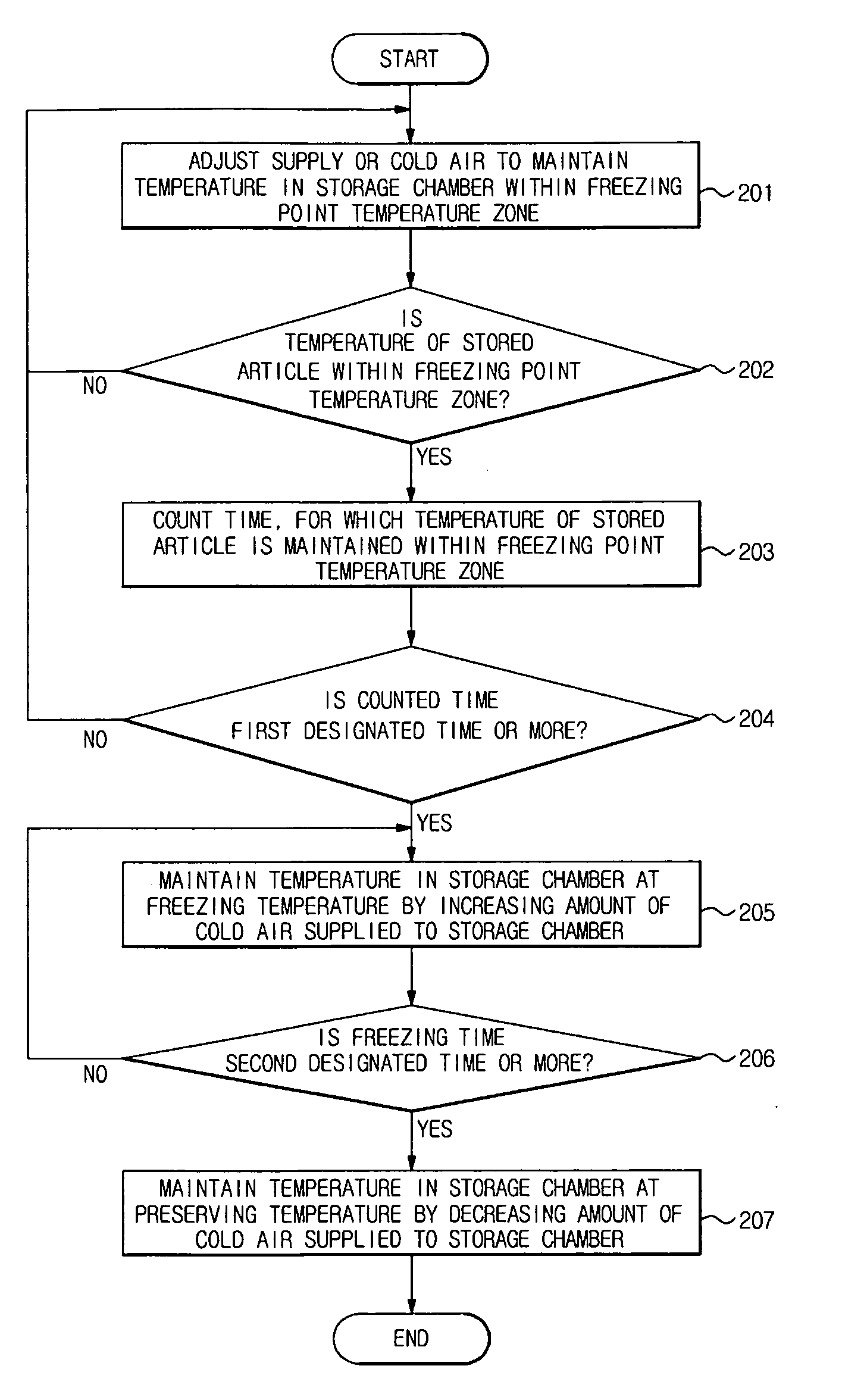
Disclosed herein are a refrigerating apparatus and a method of controlling the same. The method includes lowering a temperature in a storage chamber to a freezing point temperature zone by adjusting cold air supplied to the storage chamber, and lowering the temperature in the storage chamber to a temperature below a freezing point by increasing an amount of the cold air supplied to the storage chamber, when it is determined that a temperature of articles stored in the storage chamber is stabilized in the freezing point temperature zone by the cold air. When the surface temperature and the center temperature of the stored articles are cooled close to the freezing point and are then cooled again to the freezing temperature below the freezing point, super-cooling of the stored articles is carried out for a short time, the surfaces and the centers of the stored articles start to freeze simultaneously.

Description

CROSS-REFERENCE TO RELATED APPLICATIONS[0001]This application claims the benefit of Korean Patent Application No. 2009-0058127, filed on Jun. 29, 2009 in the Korean Intellectual Property Office, the disclosure of which is incorporated herein by reference.BACKGROUND[0002]1. Field[0003]The embodiments relate to a refrigerating apparatus, which improves freezing quality of stored articles, and a method of controlling the same.[0004]2. Description of the Related Art[0005]A refrigerating apparatus is an apparatus, in which the temperature of the inside of a sealed storage chamber is set to be lower than the external temperature, to store articles for a long time. The inside of the refrigerating apparatus is refrigerated by cold air generated by absorption of surrounding heat by a refrigerant when the refrigerant in a liquid state is evaporated in a refrigerating cycle, through which the refrigerant is circulated, and the stored articles are refrigerated through the refrigeration of the i...

Claims


Application Information

Patent Timeline
Patent Type & Authority Patents(United States)
IPC IPC(8): F25D25/00
CPCF25D2700/16F25D29/00F25D17/045F25D2700/122F25D17/065F25D17/00
Inventor LEE, SANG HOONLEE, JI YOUNGINATANI, MASATOSHI
Owner SAMSUNG ELECTRONICS CO LTD
Learn More